I. Overview
1.1 Main uses and scope of application
The automatic spring testing machine is a new type of spring testing machine that combines advanced electronic technology and efficient and precise mechanical transmission. This series of automatic spring tensile and compression testing machines are based on the international JB / T7796-2005 \"Technical Conditions for Spring Tension and Compression Testing Machine\" Made by technical requirements. Equipped with high-precision sensors for precise loading and positioning. It is mainly applicable to the testing of tensile force, compression force, stiffness, fatigue, etc. of elastic devices such as springs, rubbers, and reeds under a certain working length. Widely applicable to spring manufacturing companies and users.
1.2 Product features
1.2.1 It can measure the tension, pressure, stiffness, displacement of the spring and display the date and number.
1.2.2 Three units display: N, Kg, Lb
1.2.3 Can specify 1, 2, 3, 4, 5 paragraphs.
1.2.4 There are two modes: long-charge and long-charge
1.2.5 Sampling rate is adjustable, a variety of measurement methods can be selected
1.2.6 The use of large-scale integrated circuits improves the test accuracy, and the human-machine Chinese dialogue is intuitive and clear.
1.2.7 The special spring testing program designed according to national standards has high efficiency, complete functions and easy operation.
1.2.8 The precise measurement range of the measuring range is improved from two aspects of principle and program software.
1.2.9 Not only suitable for batch testing and sorting of springs on the production line, but also suitable for precision sampling in the laboratory.
1.2.10 There are two levels of limit protection for program control and machine. The pre-loading and deflection compensation correction ensure the accuracy of the measured value.
1.3 Specification parameter table
|
model |
10 |
20 |
50 |
100 |
200 |
500 |
|
Load capacity |
10N |
20N |
50N |
100N |
200N |
500N |
|
Minimum division value |
0.0001N |
0.001N |
0.001N |
0.001N. |
0.01N |
0.01N |
|
Unit selection |
N, Kg, g, lb |
|||||
|
Accuracy |
± 0.5% |
|||||
|
Length (displacement) accuracy |
0.01mm |
|||||
|
Maximum stroke |
200mm |
|||||
|
Speed range |
1-500mm / min |
|||||
|
Standard platen diameter |
φ20mm |
φ60mm |
||||
|
Manual button can be moved at one time |
1mm, 0.1mm, 0.01mm |
|||||
|
Test selection |
Compression, stretch |
|||||
|
Spring test options |
1. Set the length to measure the load 2. Set the load to measure the length 3. Set the deformation to measure the load 4. Set the load to measure the deformation |
|||||
|
Dimensions |
450mm * 380mm * 550mm |
|||||
|
weight |
About 60kg |
|||||
|
power supply |
220V 0.5A |
|||||
|
Machine characteristics |
1. It can automatically test free length 2. Automatic compensation for deformation of load sensor and tension spring test hook 3. Overload protection function and emergency stop function of load cell 4. Can be connected to a micro printer |
|||||
Second, the overall product structure
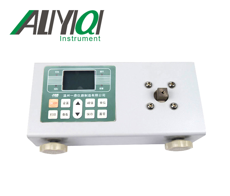
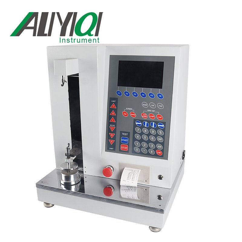
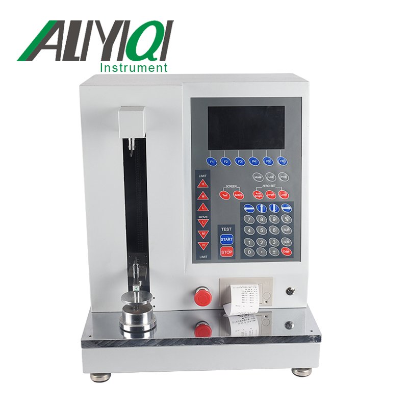
2.1 Shape and structure


2.2 LCD screen function

2.2.1 Function keys: The six function keys F1 ~ F6 are common to all the interface of the instrument, and correspond to the keys at the bottom of the screen after power on.
2.2.2 High-speed / medium-speed / low-speed up, low-speed / medium-speed / high-speed down: these 6 keys have two functions of short press and long press, short press is used to adjust the single step position of the measuring block, the user can adjust Requires manual adjustment of the position of the measuring block. For example, short press the high-speed upward pointing measuring block upward to run 1mm at a higher speed, the middle-speed upward pointing measuring block upward to run 0.1mm at a medium speed, and the low-speed upward has already run at a low speed upwards by 0.01mm.
And long press these buttons, you can make the measuring block run upward at a certain speed, the stop button is pressed, or the protection mechanism is activated. The high, medium and low speeds correspond to 100mm / min, 10mm / min and 1mm / min respectively. The function of the down button is the same as the up button.
2.2.3 Unit key: Unit switching.
2.2.4 Print key: effective in real-time measurement interface and data saving display interface. Press the print key in the real-time measurement interface to print the currently displayed segment data; in the save data interface, there are two printing methods, one is to print the current group of data, or print a group of all repeated measurement data.
2.2.5 Setting key: Enter the system setting interface.
2.2.6 Automatic origin: press this key, the spring will return to the free state and record the free length.
2.2.7 Position clearing: This key has two functions: short press and long press. Short press is used to clear the position. When the position is zero, press this key again to display the absolute position value again. Press and hold the zero key for a long time to calibrate the position. For the position calibration, the following steps must be taken: First, select the spring mode, compression and extension. Compression mode calibration is to calibrate the position of the measuring block to the bottom platform, and the extension mode , That is, you need to calibrate the position with the calibration hook to determine the absolute position during stretching. If the absolute position is inaccurate due to abnormal power failure or other reasons, you can use compressed mode position calibration to calibrate to obtain the corresponding absolute position.
2.2.8 Force value reset: Press this key to reset the displacement value. The force value reset must be effective when the motor is stopped.
2.2.9 Start key: press this key to start the test.
2.2.10 Stop key: press this key to terminate the test.
2.2.11 Up / Down / Left / Right: Used to select the number of digits when setting the spring.
2.2.12 Numeric keys: used for spring setting.
2.2.13 Switch / reverse switch / confirm key: used to select and confirm the controls in the interface.
3. Use and operation
3.1 Operation and instructions in use
3.1.1 Measurement interface

a. The real-time measurement interface mainly displays the current real-time displacement and force values. During the measurement process, the test point data is recorded, and the current spring number and the number of repetitions are also displayed.
b. In the real-time measurement interface, you can switch the spring type, measurement mode, number of measurement segments and units; after switching, the system will save the corresponding settings.
c. Type of spring: compression spring can only be set to compression, and tension spring can only be set to tension.
d. Measurement mode: it is divided into load-length and long-load. The difference between these two modes is that the reference is different. Long-load records the spring position according to the corresponding force value; load-length records the spring according to the corresponding position Force value.
e. Number of measuring segments: test the corresponding number of spring test points according to the set number of measuring segments, one segment is to find the force value or position of the first test point.
Real-time spring measurement, depending on the type, and the selected displacement (relative and absolute) mode. The setting value of its running measurement will also be different.
Take the compression spring as an example, in the load-long mode, select the displacement relative mode, then the reference displacement of segment 1 to segment 5 needs to be increased, otherwise it will not work properly. However, if the absolute displacement mode is selected, the base displacement of segment 1 to segment 5 needs to be decreased, otherwise it will not work properly.
At the same time, the final position of the measurement block cannot exceed the logical limit position of the measurement block, otherwise it will not work properly.
3.1.2 System settings
System settings include spring parameter settings, operating parameters, time settings, and factory reset.
3.1.3 Spring parameter setting

a. Test number: The test number can be set up to 32. After pressing \"Add \", the test number increases by one group. Enter the spring parameters to be tested and press \"Save \". As shown below:

b. Number of repetitions: The maximum number of repetitions can be set to 99. After pressing \"Add \", the test number increases by one group. Press \"SUP \" and \"SDN \", and the cursor moves to \"repetitions \" Enter the required value and press \"Save \".
c. Running speed: The running speed during the spring test is expressed as mm / min. The larger the value, the faster the speed.
d. Displacement (mm): the position of the spring test period.
e. Reference value: the force value corresponding to the segment point.
f. Tolerance: The setting for determining the qualified range of the spring can be set from 0% to 99%. For example, when it is set to 1%, the upper limit is 4.95 and the lower limit is 5.05. When the spring is tested, if the force value is within the upper and lower limits Inside is qualified.
g. Upper limit value / lower limit value: These two parameters do not need user input, and the instrument will automatically derive these two parameters based on the reference value and tolerance.
After setting the spring parameters, modify the value of the selected number to select the spring setting. Modify the selected number and exit.
3.1.4 Operating parameters

a. Acceleration and deceleration setting: The acceleration and deceleration setting refers to the acceleration setting of the upper pressure block during measurement. When it is set to 0, it is turned off; when set to 1, it is turned on. The acceleration setting and the measurement point stop setting are in conflict. Only when the measurement point stop setting is set to 0, the acceleration and deceleration settings are valid.
b. Measurement point stop setting: The measurement point stop setting refers to the stop setting of the instrument at each segment point during measurement. When set to 0, it is turned off; when set to 1, it is turned on. In the open state, if the number of segments is set to 5, the instrument will stop once at these 5 segment points during measurement; if in the off state, the instrument will not stop at the segment point during measurement.
c. Continuous test setting: Repeat the test setting. When set to 0, it is turned off; when set to 1, it is turned on.
d. Starting speed: The starting speed setting is only valid when the acceleration / deceleration setting is turned on. The starting speed can be set from 1 to 5, when it is set to 1, that is, the acceleration during measurement is from 1mm / min to 100mm / min. , The faster the acceleration starts. The speed setting unit is mm / min, and the starting speed cannot be set to 0.
e. Without first-stage stiffness: When the first-stage stiffness is not set to 1, it is in the on state. For example, 5 segments are set. When the instrument calculates the average stiffness, the first-stage stiffness will not be calculated; if it is set to 0, then Is off.
f. Sampling rate: the sampling times of the instrument per second, which can be set from 1 to 100.
g. Automatic zero-point high-speed: The high-speed setting of the automatic origin can be set from 1mm / min to 100mm / min. After pressing the automatic origin button during measurement, the spring will return to a relatively close to the origin at the set automatic zero-point high-speed value.
h. Automatic zero-point low speed: Automatic zero-point low speed is a value set on the basis of automatic zero-point high speed, which can be set from 1mm / min to 10mm / min. When the spring returns to a position relatively close to the origin, automatic zero-point low speed starts To make the spring return to the original position more accurately.
i. Zero point high ratio / zero point low ratio: These two parameters are used to determine the force value of the automatic origin. For example, the zero point high ratio is set to 200, that is, the force value is full range * 200/10000, which is 2% of full range. The low zero ratio is set to 3, that is, the force value is full scale * 3/10000, which is 0.03% of full scale. After starting the automatic origin, when the force value is close to 2% of the full scale, the instrument will stop at the position of the automatic origin according to the low percentage of the force value after the force value pauses for a few seconds.
j. Limit protection switch: physical limit switch protection, when set to 1, it is turned on; when set to 0, it is turned off. This function is not recommended for the user to set to the closed state, but due to the limit protection of the spring machine, the default state of the measuring disk is not able to run the bottom plane. If the measured spring is very short, consider closing the limit protection to reach the measuring disk bottom.
k. Displacement absolute mode: when set to 1, it is displacement absolute mode; when set to 0, it is displacement relative mode. For the relative measurement mode and the absolute measurement mode is the difference between the set deformation and the set length. The relative measurement mode is how many millimeters are stretched or compressed, while the absolute mode is expressed as how many millimeters are stretched or compressed.
Relative measurement mode, the displacement required to set the number of spring segments, LENGTH1
At the same time, the force value setting is also required, FORCE1
In the absolute measurement mode, the setting parameters will be different for different spring types
Compression spring, LENGTH1> LENGTH2>…> LENGTH5
Tension spring, LENGTH1
3.1.5 Time setting

Time setting is used to set the time displayed on the measurement interface and the printing time
3.1.6 Restore factory settings
Press this key, the instrument restores the factory settings and restarts automatically
3.2 Operation steps
3.2.1 Confirm that the power cord is connected.
3.2.2 Turn on the power switch.
3.2.3 Select the spring type, unit, measurement mode and number of measurement segments.
3.2.4 Enter spring parameter setting and running parameter setting, input spring parameters, save and exit.
3.2.5 Return to the measurement interface, press \"START \" to start the detection, and press \"Print \" to print the measurement data when finished.
3.3 Data export
3.3.1 Using the communication interface, real-time measurement data can be exported through the communication protocol provided by our company.
Fourth, daily maintenance and maintenance
4.1 The environment should be kept clean to prevent liquids, iron filings, etc. from intruding into the instrument and damaging electronic components.
4.2 Please clean the instrument with a soft cloth, immerse the cloth in the water soaked with detergent, wring it out and remove the dust and dirt.
Note: Do not use volatile chemicals to clean the instrument (such as volatile agent, thinner, alcohol, etc.)
4.3 Do not operate the machine in the following environment
a. Humid environment
b. Dusty environment
c. Where oil or chemicals are used
d. Places with earthquake sources around
4.4 When not in use for a long time, the power plug should be unplugged to prevent dust and moisture.
V. Random accessories
|
1 |
Machine |
1 set |
|
2 |
power cable |
1 |
|
3 |
Instructions |
1 serving |
|
4 |
Certificate of conformity |
1 serving |
|
5 |
Warranty Card |
1 serving |
|
6 |
Standard hook |
1 |