1. Function
High-speed impact torque tester is an intelligent multifunctional measuring instrument designed and manufactured for testing and detecting various torques. It is mainly used to detect and correct the torque of various electric pneumatic screwdrivers and torque wrenches. Various products involve the test of tightening force and the torsional destructive test of parts. It has the characteristics of simple operation, high precision, full function and convenient portability. It is widely used in various industries such as electrical, light industry, machinery manufacturing, scientific research institutions and so on.
2. Main features
1. High precision, high resolution, fast sampling speed, full screen display.
2. Adopt high-precision torque sensor with torque direction display.
3. The setting of upper and lower limits, red and green indicator lights and sound and light alarm of the buzzer.
4.The three units are interchangeable and available for selection (N · m, kgf · cm, Ib · in).
5. The three modes of real-time, peak and auto-peak can be switched at will.
6. The USB interface is used to communicate with the PC, and the synchronous test function can be connected to the computer for testing. The computer displays the test force curve and the detailed test force record during the test.And can save, print, do all kinds of analysis.
7. Peak hold, automatic release function, free setting of release time.
8. Large storage capacity, can save 99 sets of test data.
9. Automatic shutdown function without operation, time can be set freely.
3. Specifications
|
model index |
With printer |
AGN -1P |
AGN -2P |
AGN -3P |
AGN -5P |
AGN -10P |
AGN -20P |
|
Without printer |
AGN -1 |
AGN -2 |
AGN -3 |
AGN -5 |
AGN -10 |
AGN -20 |
|
|
measuring range / Minute Degree |
N · m |
1.0000 /0.0001 |
2.0000 /0.0001 |
3.0000 /0.0001 |
5.0000 /0.0001 |
10.000 /0.001 |
20.000 /0.001 |
|
Kg · cm |
10.210 /0.001 |
20.421 /0.001 |
30.631 /0.001 |
51.052 /0.001 |
102.10 /0.01 |
204.21 /0.01 |
|
|
Ib · in |
8.862 /0.001 |
17.724 /0.001 |
26.586 /0.001 |
44.311 /0.001 |
88.62 /0.01 |
177.24 /0.01 |
|
|
Accuracy |
± 1% |
||||||
|
Peak sampling frequency |
2000HZ |
||||||
|
Test speed |
≤15000rpm |
||||||
|
power supply |
8.4V 1.2VX7 Ni-Cyan battery pack |
||||||
|
Charging time |
4 ~ 6 hours |
||||||
|
Battery continuous use time |
About 10 hours |
||||||
|
Battery Life |
≥300 times |
||||||
|
size |
With printer: 230mm × 95mm × 180mm Without printer: 230mm × 70mm × 125mm |
||||||
|
Net Weight |
With printer: 5KG Without printer: 3KG |
||||||
|
Power Adapter |
Input: AC 220V 50HZ Output: DC 10V 300mA |
||||||
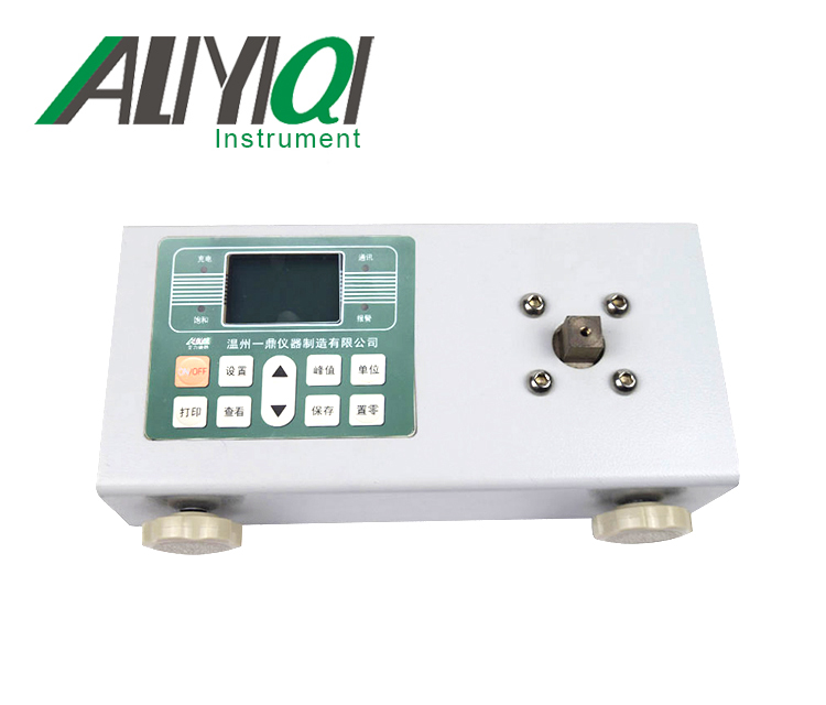
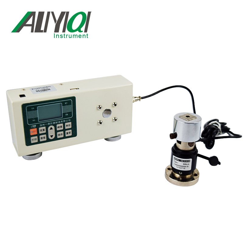
Fourth, the name and function of each part
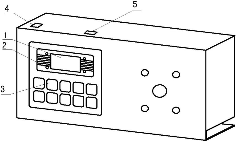

No printer
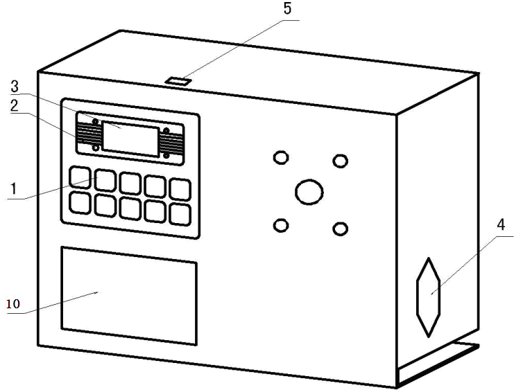
With printer
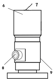
1. LCD display window 6. Test head
2. Indicator 7. Quartet connector
3. Function buttons 8. Sensor cable interface
4. Power socket 9. Torque sensor
5. Communication interface 10. Printer
1,LCD display window
a, boot display
Display the manufacturer's information after booting, welcome your use and display the product model
b. User main interface display
1Measurement mode: divided into three modes: real-time, peak, and automatic peak, users can freely choose according to their needs
2Measuring the direction of twist:\"Chun \" refers to the clockwise direction, \"Reverse \" refers to the counterclockwise direction.
3Measure the force value.
4Units of measurement:The three units of N · m, kgf · cm and Ib · in can be freely selected as required.
5Battery level indicator: When the battery level is low, it displays \" \"Or insert the matching battery upper limit red indicator light flashes quickly after the red indicator light亮,You need to charge.
2,Indicator light
1Charging: When the matching power adapter is used for charging, the red light is on.
2Saturation: When the matched power adapter is fully charged, the green light is on.
3Communication: When using an instrument equipped with a printer function.
4Call the police:Upper and lower limit alarms, when the measured force value is higher than the upper limit value, some lights are red and the buzzer alarm; when the measured force value is lower than the lower limit, some lights are green and the buzzer alarm.
3.function button
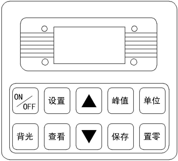
a.\"ON / OFF \" key: power switch, turn on and off.
b. \"Print \" key: used on instruments equipped with a printer. Press this key to print out the measurement data saved in the instrument (except for those without a print function).
c. \"Settings \" key: Users can enter the setting menu through this key when in measurement mode.
d. \"View \" key: in measurement mode, you can use this key to view the stored measurement data, and press it again to return to measurement mode.
e. \"▲ \" key: In the user setting interface, press this key to modify the setting items up and down. During parameter setting, press this key to modify the data in the current position; in the viewing interface, press this key to view the previous one data.
f, \"▼ \"Key: In the user setting interface, press this key to modify the setting items downwards. During parameter setting, press this key to move digit by digit to select the digit to be modified; in the view interface, press this key to view the next data .
g, \"Peak \" key: used to switch between real-time, peak, and auto-peak measurement modes
h, \"Save \" key: used to save the measured data.
i, \"Unit \" key: used to switch N · m, kgf · cm, Ib · in three units.
j, \"Zero \" key:
① During real-time measurement, press this key to correct the zero point;
②,During peak and auto peak, press this key to clear the peak and return to zero;
③ When viewing the interface, press this key three times to delete all records;
④. On the user setting interface, press this key to return to the previous interface without saving data.
4.Power outlet:Used to connect or charge with an external power source.
5.Communication Interface:USB interface output, used to connect to the computer.
6.Test head:Transfer torque load to the sensor.
7.Screw with cylindrical head:Tighten the test head.
8,Sensor cable interface
9,Torque sensor
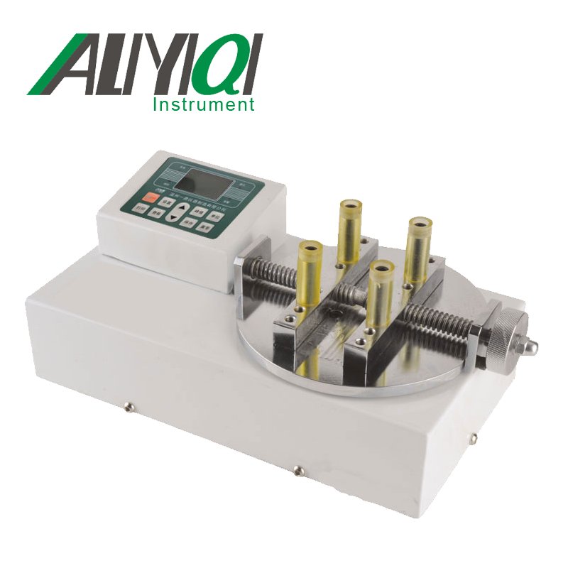
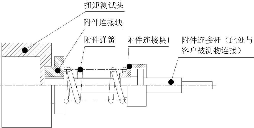
10. Connector:(Connected to the buffer) Test range, installation (as shown in the figure below) and inspection of the buffer
1,Buffer test range
|
model |
Buffer test range |
Remarks |
|
AGN-3. AGN-5, AGN-10, AGN-20 |
0.5-3N.m |
Use spring with wire diameter d = 3.5 |
|
AGN-1, AGN-2 |
0.15-0.6N.m |
Use spring with wire diameter d = 2.5 |
②3. Installation of the buffer: According to the needs of the test, select the bearing and the spring, and then rotate it counterclockwise to install the spring.
③3. Buffer inspection:
A. Check the buffer before use. Dust, lack of grease and bending of the bushing will affect the accuracy of the torque test.
B. Periodically check the buffer. Repeated use of the buffer for a long time will cause the buffer to wear and affect the accuracy of the torque test. If it is worn, it needs to be replaced.
10.printer:Print out the measurement saved inside the instrumentdata
5. Working environment
1. Operating temperature: -10 ℃ ~ 40 ℃.
2. Operating humidity: ≤90% RH.
3. There is no vibration source and no corrosive environment around.
6. Operation steps
1. Before using the high-speed impact torque tester, first check whether the power of the instrument is sufficient,If the power is insufficient, please charge it first (it can also be used while charging).
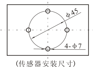
2. Fix the sensor on the test bench with M6 screws, and make sure that the bench is not moved at the maximum torque when installing.
3.Under normal circumstances, turn on the power switch, the displayed torque value is zero. If it is not zero, press the reset button to reset the torque value.
4. Before testing, the first need to set the upper and lower limits, minimum storage value, minimum peak hold value, automatic peak time, automatic shutdown time, gravity acceleration, etc. The specific steps are as follows:
a. Press the\"Settings\" key on the user's main interface for the first time to enter the user setting interface. The display shows as follows:
Use the up or down key to select the setting item. When the user's setting item is selected, press the setting key to enter the parameter setting interface.
b. Parameter setting interface
In the user setting interface, press \"Settings \" to enter the parameter setting interface and display as follows:
Explanation of setting parameters: (The above limits are set as an example)
Via \"▲ \" key and \"▼\"Key to modify and shift the data, press \" Save \"key to save the setting data, the display interface returns to the user setting interface, and the next setting item can be set. (Such as pressing \" Zero \"key Then return to enter the user setting interface without saving the modified data), after all the setting items are set and saved, press \"ON / OFF \" key to shut down directly, then press \"ON / OFF \" key to boot, enter User main interface. The set data cannot exceed the maximum load value.
Upper limit setting:The user sets the upper limit value, which can be set freely according to needs. When the upper limit value is reached, it will automatically sound and light alarm, the upper limit value is not higher than the full range.
②、Lower limit setting:The lower limit is set by the userWhen it reaches the lower limit, it will automatically light alarm, and the lower limit shall not be higher than the set upper limit.
③、Minimum storage value setting:The user sets the minimum storage value according to storage needs, and data smaller than this value will not be stored.
④、Minimum peak hold value setting:According to the peak value, the user needs to set freely for automatic peak measurement, and data smaller than this value will not be saved by the peak value.
⑤、Automatic peak time setting:According to the automatic peak measurement state, the user needs to maintain the peak time from 1Seconds ~Set freely in 99 seconds.
⑥、Automatic shutdown time setting:In no operation state, the automatic shutdown time is from 0 minutes~9 minutes can be set freely (when set to 0 minutes, it means to release the automatic shutdown).
⑦、Gravity acceleration setting:The user can set the acceleration value of gravity according to the location of the area. The machine defaults to 9.794.
⑧、Restore the initial settings:Improper user operation or confusion when changing data multiple times, you can use this setting to change1~7 The data is restored to the factory state.
5. Before testing, select the second measurement mode
It is displayed as the real-time measurement mode on the user's main interface. When the first time press the\"\" peak\"key to enter the peak measurement mode, the second time press the\"\"peak\" key to enter the automatic peak measurement mode, then (that is, the third time) Press \"Peak \" to return to the real-time measurement mode and cycle in turn, as shown in the following figure:
6. Before testing, choose the second measurement unit
Press the\"Unit\" key for the first time in any measurement mode to displayThe N · m unit enters the Kg · cm unit display, and the second press of the\"\" Unit\"key enters the Ib · in unit display.
7. During the test, press\"Save\" to save the measurement data.
Note: During the test, when the measured value exceeds the upper limit, the communication indicator will show red, and the buzzer will also give an alarm; when the measured value is lower than the lower limit, the communication indicator will show green, the buzzer The alarm will still occur. When the measured value exceeds 120% of the maximum load, the sensor may be damaged. When the measured value exceeds 150% of the maximum load, it will definitely cause damage to the system. When the \"Severe Overload \" warning prompt appears, it will automatically shut down, the instrument will enter the automatic protection state and must be restarted, the display will show \"Severe Overload \" warning prompt, press \"Settings \" to enter the user setting interface,\"▼\"Key to choose to restore the initial settingsItem, and then press \"Settings \", the display will show the prompt for inputting the password.\"▲ \"、\"▼\", \"Peak \", \"Save \",\"▲ \"、\"▼\", \"Peak \" and \"Save \" keys can be restored (if you can not restore, please contact the manufacturer).
8. After the test, you can press the\"View\" button to view the saved data, pass\"▲ \" key and \"▼The\"\" key displays the last saved data or the next saved data.
9. After using the torque tester, press \"ON / OFF \" to turn off the power switch and put the tester back into the instrument box.
7. Torque test procedure of screwdriver
1. First install the buffer on the torque test head of the torque tester, and then assemble the screwdriver batch on the buffer.
2. Press the screw switch to the automatic state, use your fingers to reverse the force, and relax the spring of the buffer a little.
3. Press the peak key to select the peak hold state of PEAK.
4. Press the clear button, the torque value displayed on the LCD screen is zero.
5.Press the screwdriver's switch to automatic, twist the screwdriver until the screwdriver stops automatically.
6.When the screwdriver stops rotating, the torque value displayed on the LCD screen is the torque output by the screwdriver. Repeat the above operations 2 to 5 to verify the output torque of the screwdriver. Loosen or tighten the torque adjustment nut of the screwdriver to make the torque of the screwdriver meet the needs of use.
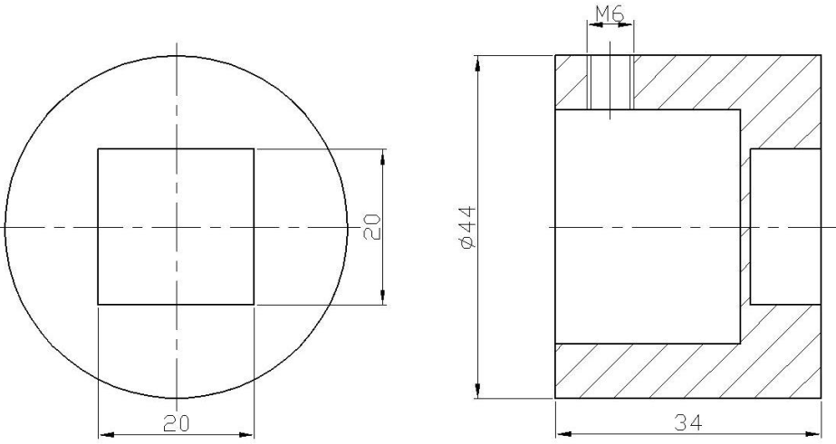
8. Torque test head and connection size
1. The vertical load on the torque test head cannot exceed 1kg.
2. Do not hit the test head of the torque tester to avoid damage. The following is a plan view of the torque test head:
Nine, USB output
The instrument communicates with the host computer via USB. The communication protocol adopts MODBUS-RTU protocol. The specific connection method of the instrument and the software is as follows:
1. Connect the instrument to the computer with a direct connection, connect the instrument with a USB male connector, and connect the RS-232 female connector to the computer.
2. Turn on the instrument power so that the instrument is in the measurement interface.
3. Put the supplied CD-ROM into the computer CD-ROM drive and open the serial port software path: CD-ROM \ software \ AutoTest.exe.
4. Click the \"System \" button at the bottom of the software window to pop up the \"System Settings \" dialog box, and select the serial port corresponding to the computer in the communication port. The specific operation steps are as follows:
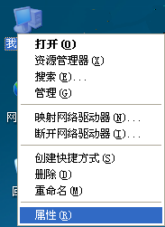
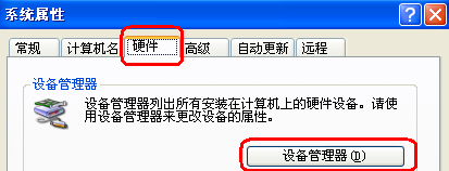
① Right-click \"My Computer \" select \"Properties \", select \"Hardware \" option bar in the pop-up \"System Properties \" dialog box, and then click \"Device Manager \" button (as follows (Pictured):
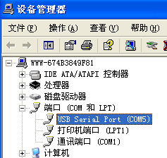
②. In the pop-up \"Device Manager \" dialog box, check the serial number of the sub-item of the port item class (as shown in the figure below):
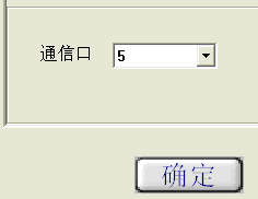
③ Return to the\"System Settings\" dialog box popped up by the software, select the corresponding serial port number in the communication port (metaphorically as\"\" 5 \"), and then press OK, as shown in the following figure:
④, close the software, double-click againAutoTestAfter .exe, you can check whether the serial port has been connected. There are many ways to check: apply a force to the sensor of the instrument, check whether the torque value at the top of the software window corresponds to the jump, if it jumps, it means that it is connected, otherwise on the contrary.
⑤ Click the\"Settings\" button at the bottom of the software window to pop up the\"Parameter Setting\" dialog box, and fill in the corresponding data according to the test needs. The specific parameter size is filled in as described in step 6-3-b. After filling in, press the\"OK\" button. After the setting is successful, the data displayed at the bottom of the software window will change accordingly.

⑥ Make sure that the serial port is connected, and press the\"Start\" button to perform the synchronous test.
⑦ After the test is completed, press the\"Stop\" button and click\"Save\" or\"Stop\". Save the test curve and save it in the software, otherwise stop it.
⑧, software interface introduction:
a. There is a torque value display area, a time display area and a test number at the top.
b. On the left, there are upper limit line, lower limit line, indicator line, specification display, display curve, clear curve and derived curve.
Upper limit line: When the box in front of the upper limit line is ticked, the curve display window has a horizontal line for the upper limit torque value.
Lower limit line: When the square in front of the lower limit line is ticked, the curve display window has a horizontal line showing the lower limit torque value.
Indicator line: the mouse is in a cross shape in the curve display window, and the position of the cross mouse isMove the corresponding torque value display area and time显The display area will change accordingly.
Specification display: As the name implies, it shows the specifications (model and range) of the instrument.
Display curve: Click this button to pop out the\"Select curve\" dialog box, select the test items to be displayed, and then select the number of tests to be displayed.
Clear curve: just erase the currently displayed curve, but not delete this curve from the software.
c,Below are the settings, start, stop, report, system, help, delete and exit buttons.
The settings, start, stop and system buttons have been introduced in the front.
Report: Click this button to pop out the \"Curve data selection preview \" dialog box, first select the size of the sampling point frequency, then select the test items to be displayed and the number of tests to be displayed, and finally click\"Execl\"\"Button.
Ten, matters needing attention, maintenance and repair
1. Do not overload the torque test, be sure to test the torque within the test range of the torque tester, otherwise the instrument will be damaged and more likely to be dangerous.
2. Do not tap the LCD screen to place objects on the LCD screen.
3. Do not press the function keys with nails, sharp objects or pointed objects.
4. Do not use the torque tester where water, oil or other liquids are splashed. Store the torque tester in a cool, dry and vibration-free place.
5. Do not open the small cover on the back or adjust the trimming resistor inside.
6. Do not loosen the fixing screws of the torque test head.
7. Please use the matching power adapter to charge, otherwise it will cause circuit failure and even fire.
8. Insert the AC power adapter completely into the socket before use. Loose plug may cause a short circuit and cause electric shock or fire.
9. Do not use any power source other than the rated voltage of the power adapter, otherwise it may cause electric shock or fire.
10. Please do not pull out or insert the plug with wet hands, otherwise it may cause electric shock.
11. Please clean the machine with a soft cloth, immerse the dry cloth in the water soaked with detergent, wring it out and remove the dust and dirt. Do not useChemical substances that are easily emitted, such as volatile oil, thinner, alcohol, etc.
12. Handle gently during use and handling.
13. Do not disassemble, repair or modify the machine by yourself. These actions may cause permanent malfunction of the instrument.
14. Please contact the original place of purchase or our company if a fault occurs.
15. Within one month from the date of sale, the product has quality problems under normal use and no damage to the appearance. The customer will use the original sales invoice, valid warranty card and complete packaging to the original purchase place or the company to replace the same specifications For the model product, the replacement product will continue the warranty period and terms of the original product.
16. This product is within one year from the date of sale. Under normal use, non-human faults are covered by the warranty (the user does not disassemble the machine or repair it at other repair points. The company does not guarantee the warranty). The customer has the original sales invoice and valid warranty If the card is contacted with the original place of purchase, the company will get a free warranty for one year.
17. The warranty clause of this product is only applicable to the high-speed impact torque tester products sold in the Chinese market. For products that exceed the replacement period and warranty period, the customer can check the original purchase place for maintenance matters or contact the company. Provide paid repairs.