AMF push pull gauge
- AMF:
- AMF-2,AMF-3,AMF-5,AMF-10,AMF-20,AMF-30,AMF-50,AMF100,AMF-200,AMF-300,AMF500


AMF Digital Force Gauge
user's Guide
1 Overview
AMF digital push-pull force meter is a small, simple, multi-functional and high-precision thrust and pull test instrument, which is widely used in electronic appliances, construction hardware, light industrial textiles, auto parts, lighters and other ignition devices, fire-fighting equipment, pen-making, and manufacturing Push-pull load, plug-in force test, destructive test, etc. in locks, fishing gear, chemical industry, power machinery, scientific research institutions and other industries. The digital display has high resolution, fast sampling speed, and easy to use. It is a new generation of high-efficiency and high-precision push-pull force testing instrument.
2. Features
2.1 High precision and high resolution;
2.2 Free switching of three measurement modes (real-time, peak, first peak);
2.3 Free switching of four measurement units (N/Newton, kg/kg, lb/lb, Oz/oz);
2.4 Gravity acceleration setting function: the user can input the accurate value of the gravity acceleration of the place of use by himself, so that the test and unit conversion are more accurate;
2.5 The upper and lower limits can be set for statistical analysis, and the buzzer can alarm by setting the upper and lower limits beyond the limited range;
2.6 Minimum force value shielding function: the data in the minimum range of setting can be shielded;
2.7 Automatic shutdown function: the automatic shutdown time can be set, and the automatic shutdown can achieve the effect of saving points when there is no operation for a long time.
2.8 Power supply: 2 1.5V dry batteries;
2.9 Automatic backlight, buzzer alarm function;
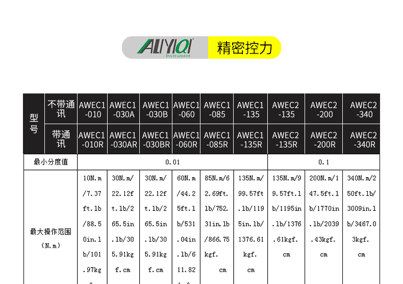
3. Specifications
|
Model specification |
AMF-2 |
AMF-3 |
AMF-5 |
AMF -10 |
AMF -20 |
AMF -30 |
AMF -50 |
AMF -100 |
AMF -200 |
AMF -300 |
AMF -500 |
|
Maximum load value |
2N |
3N |
5N |
10N |
20N |
30N |
50N |
100N |
200N |
300N |
500N |
|
0.2kg |
0.3kg |
0.5kg |
1kg |
2kg |
3kg |
5kg |
10kg |
20kg |
30kg |
50kg |
|
|
0.45 Lb |
0.65 Lb |
1.1Lb |
2.2Lb |
4.5Lb |
6.5Lb |
11Lb |
22Lb |
45Lb |
65Lb |
110Lb |
|
|
Load scale value |
0.001N |
0.01N |
0.1N |
||||||||
|
0.001kg |
0.001kg |
0.01kg |
|||||||||
|
0.001Lb |
0.001Lb |
0.01Lb |
|||||||||
|
Sensor structure |
Built-in |
||||||||||
|
Precision |
±2% |
||||||||||
|
power supply |
Two 7# dry batteries (1.5V) |
||||||||||
|
Operating temperature |
5℃~35℃ |
||||||||||
|
Transport temperature |
-10℃~60℃ |
||||||||||
|
Relative humidity |
15%~80%RH |
||||||||||
|
working environment |
No seismic sources and corrosive media around |
||||||||||
%1, shape structure
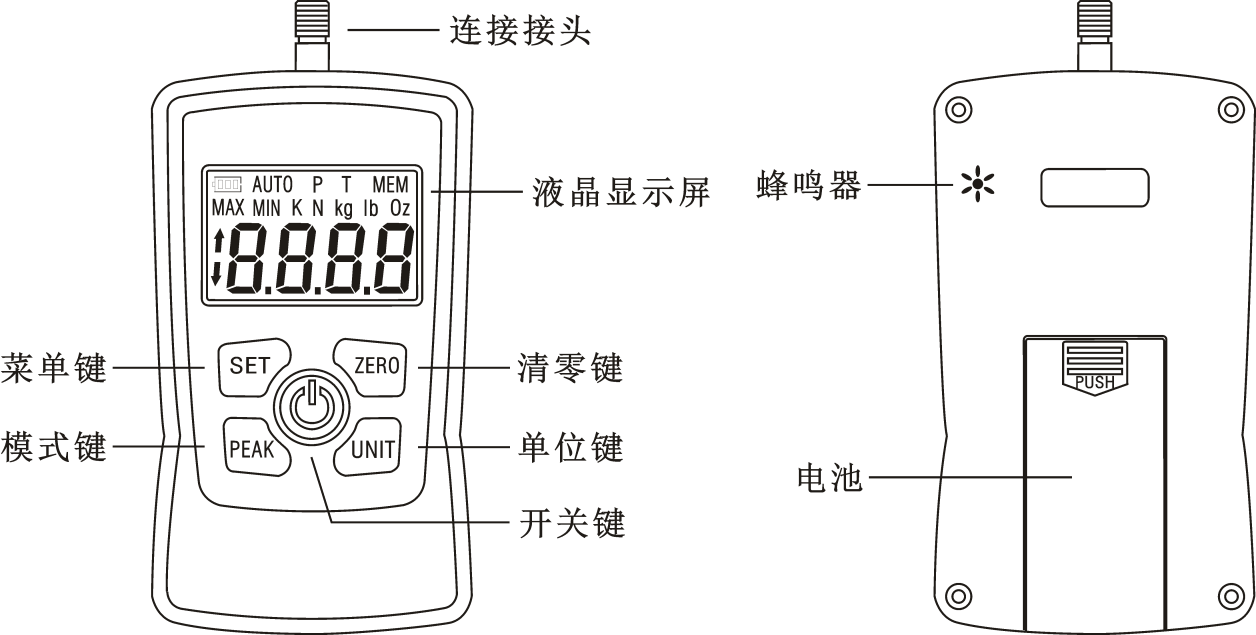
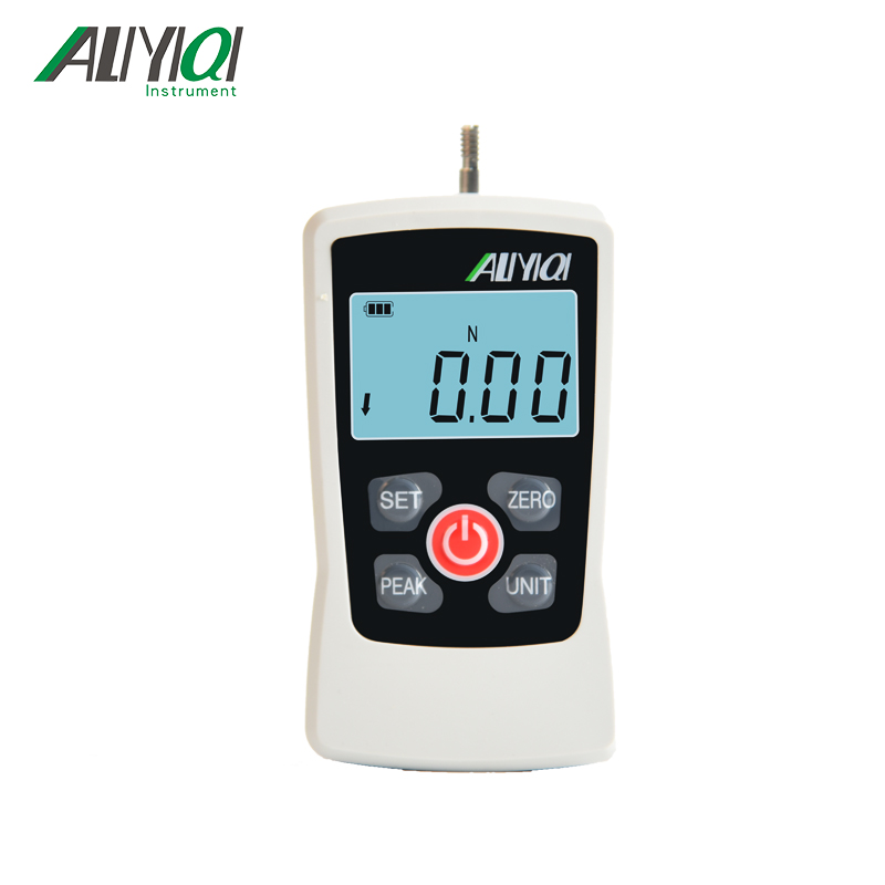
%1, display
①, battery power;
②. The screen displays "P" and "T" at the same time as the first peak mode, which means to record the first peak value measured in a period; the screen displays a single "P" as the peak mode, which means to record the measured peak value in a period Maximum force value; press the "PEAK" key to freely switch between peak and first peak modes.
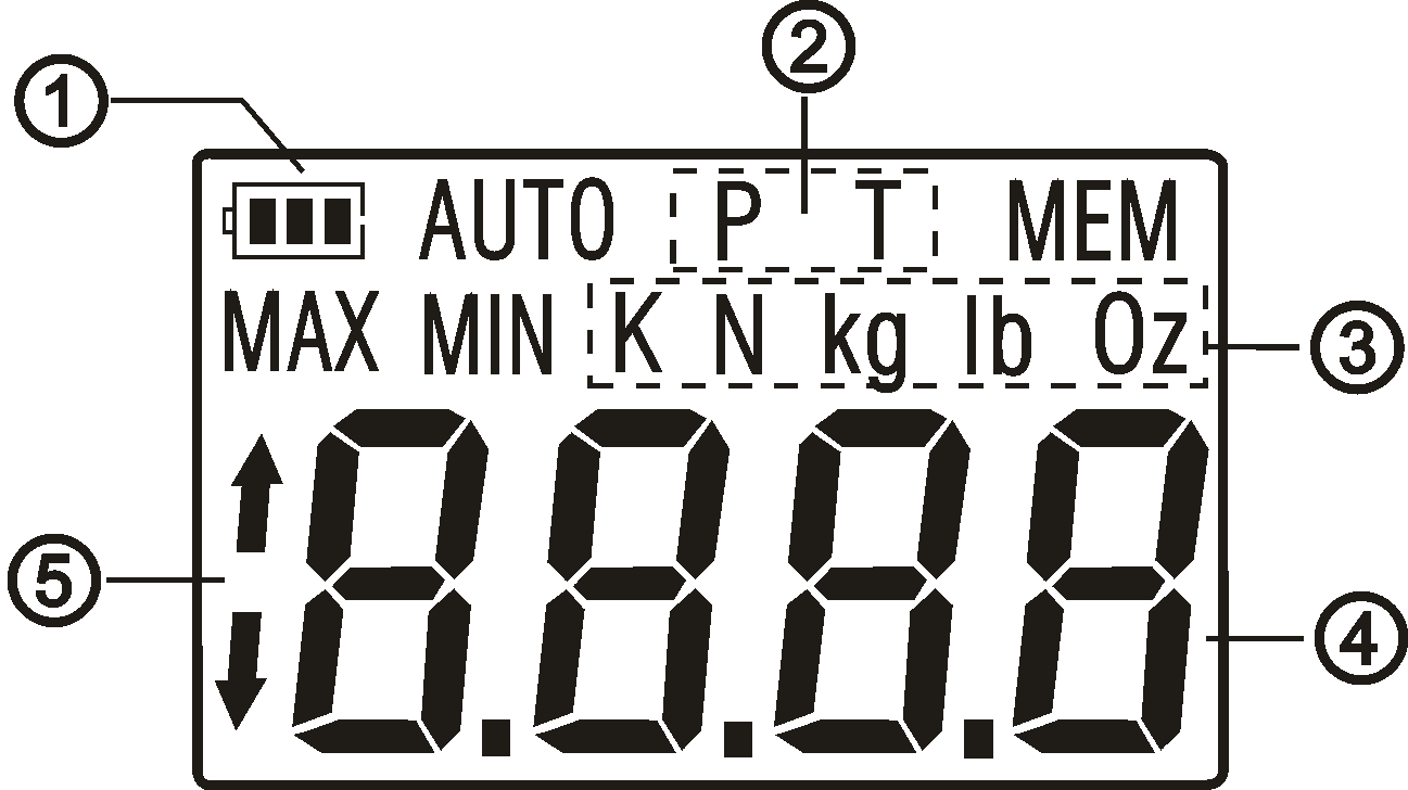
③, unit display;
④ Display of measured force value;
⑤. Push-pull force display: the upper arrow shows the pull force, and the lower arrow shows the push force.
Six, operating instructions
6.1 Boot display

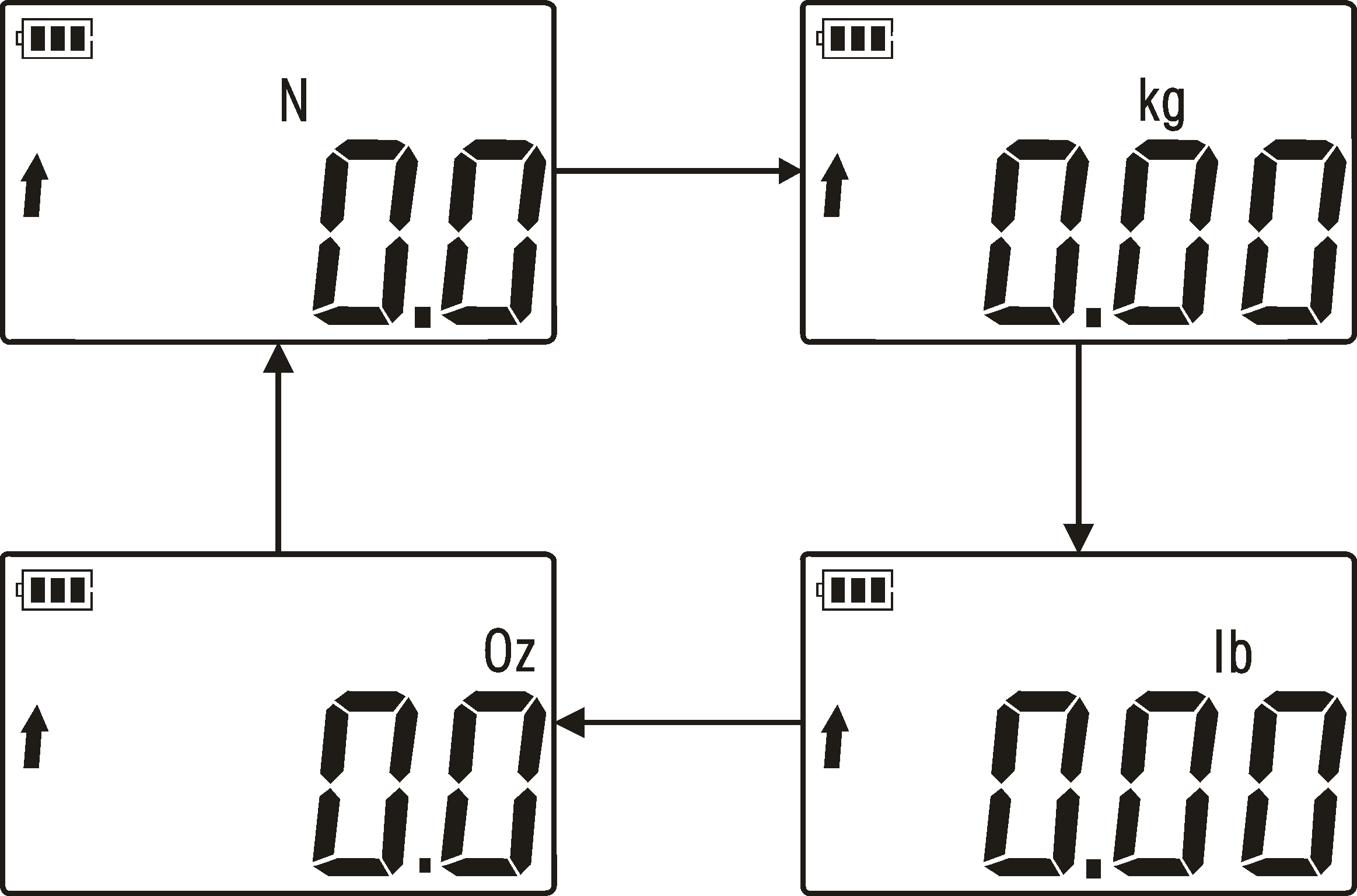
6.2 Unit switch
Press the "UNIT" key to freely select the required measurement unit.
6.3 Clear value
Press the "ZERO" key, the measured value on the screen will be cleared.
6.4 Description of measurement mode conversion
Press the "PEAK" key to freely select the required measurement mode.
6.4.1 Real-time mode
Power on and enter the measurement interface, the system defaults to real-time measurement mode, and no mode is displayed on the screen. In this mode, the displayed measurement value will change with the change of the load.
6.4.2 Peak mode
Press the "PEAK" key, the display of "P" on the screen is the peak mode. In this mode, the displayed measured value is the maximum value. (When measuring again, if the measurement value is lower than the previous maximum value, the displayed measurement value will not change; if the measurement value is higher than the previous maximum value, the displayed measurement value will update and change.)
6.4.3 First peak mode
Press the "PEAK" key and the words "P" and "T" are displayed on the screen at the same time, which is the first peak mode. In this mode, the instrument only displays the first peak value measured in a period of time, and the measured value will not be displayed again. If there is a change, press the "ZERO" key to clear it before testing again.
Seven, system settings
Press the "SET" key to enter the system setting interface; then press the "PEAK" key to scroll down to select the setting item or press the "UNIT" key to scroll up to select the setting item, press the "SET" key to confirm, and press the "ZERO" key to exit.
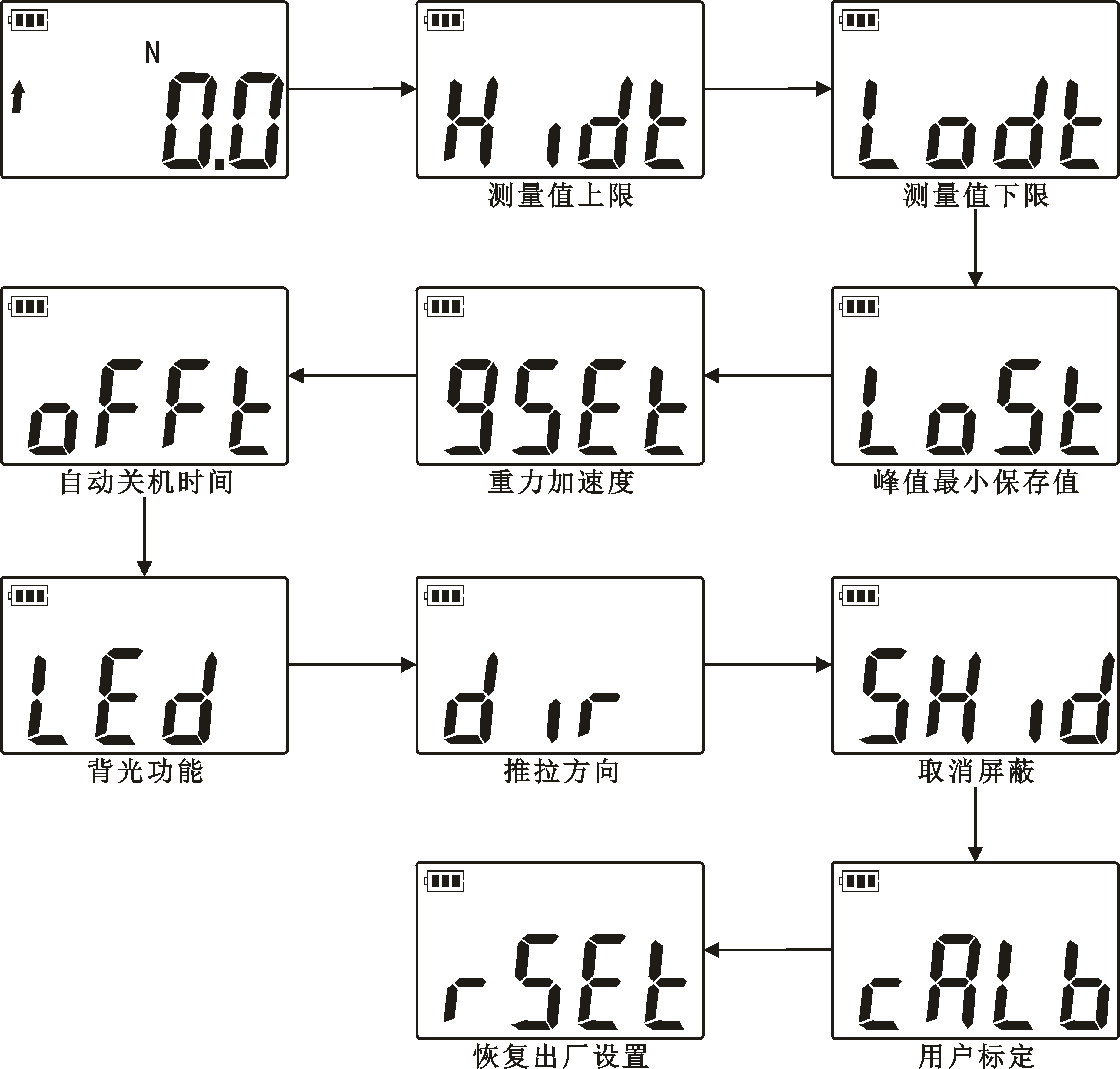
7.1 Upper limit of the measured value: Set the upper limit of the measured value. The upper limit is the full scale by default. If the measured value is higher than the upper limit, the range is out of range. The screen displays "MAX" and the buzzer alarms for a long time. As shown below:
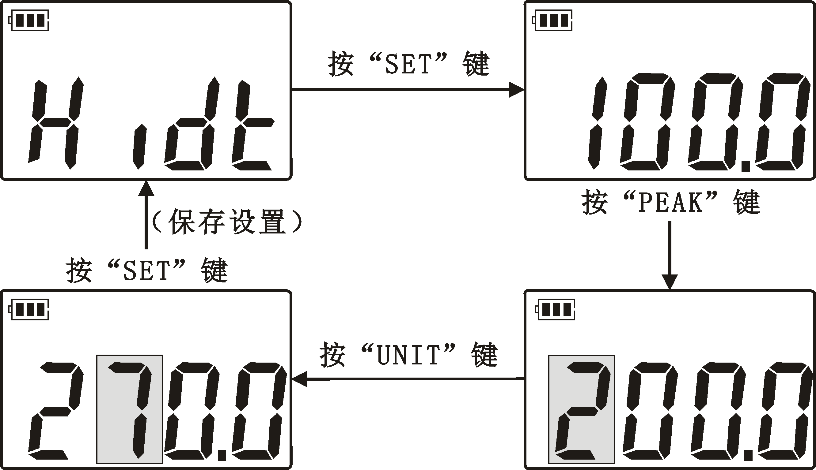
7.2 Lower limit of measured value: Set the lower limit of measured value. The default lower limit is 0. If the measured value is below the lower limit, it is out of range. The screen displays "MIN" and the buzzer alarms for a long time. The user can freely set the lower limit value, select this menu to set the value, and the operation steps are the same as the upper limit value.
7.3 Peak minimum saved value: The minimum peak saved value. In peak mode, when the current value is less than this value, the peak value will not be saved and displayed. The user can freely set the minimum saved value, select this menu to set the value, the operation steps are the same as above.
7.4 Gravity acceleration: The user can set the gravitational acceleration value according to the location of the use area, the default value is 9.800.
7.5 Automatic shutdown time: the user can freely set the shutdown time from 0-15 minutes, select this menu and press the "SET" key to enter the shutdown time setting. Press the "PEAK" or "UNIT" key to set the shutdown time value, and press the "SET" key to save the setting. The system defaults to the automatic shutdown time of 10 minutes.
7.6 Backlight function: This function has three setting modes. AUTO is automatic mode, that means the instrument will automatically turn off the backlight when there is no operation; OPEN is normally open mode, that means the instrument is always in the backlight state; CLOS is normally off mode, that means the instrument is always in backlight Disabled. Select this menu and press the "SET" key to enter the mode setting, press the "UNIT" key to switch modes freely, and then press the "SET" key to save the setting.
7.7 Push-pull direction setting: used to switch the display direction of the push-pull force gauge.
7.8 Cancel shielding: shielding the display of data below 0.5% of the full scale, "YES" means shielding, "NO" means no shielding, and the system defaults to "YES". The user can freely set this item, press "SET" to enter the setting, and then press "UNIT" to switch YES or NO freely, after setting, press the "SET" key to save the setting.
7.9 User calibration: This setting item is the instrument calibration function, select this menu, press the "SET" key to enter the password "1111" to enter the calibration calibration interface. First display "ZERO" to start zero-scale calibration. After calibration, press the "SET" key, and display "FULL" to start full-scale calibration. After calibration, press the "SET" key to save the calibration, and the instrument will automatically shut down. As shown below:
7.10 Restore factory settings: This setting is convenient for users to set up confusion, and can restore factory settings with one key. Enter the system menu, select this setting and press the "SET" key to restore the factory settings, and the instrument will automatically shut down. If you continue to use the instrument, press the power button, and the instrument has been restored to the factory default settings.
8. Test
Press the "power on" button to turn on the instrument, and use the factory default settings to directly test or set the test mode to perform the test as needed.
8.1 Choose a suitable test joint fixture and install it on the push-pull force gauge.
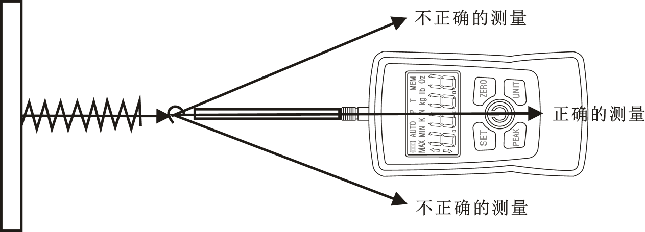
8.2 Please hold the force gauge firmly or install the force gauge on a suitable testing machine for testing. During the test, please align the force to be tested with the push-pull rod of the force gauge so that the accurate load value can be measured.
8.3 After the test is completed, unload the load, turn off the power, remove the fixture, clean the objects and put them back in the tool box for next use.
%1, safety precautions
9.1 Matters needing attention:
9.1.1 If the operation is wrong, it may damage the instrument or cause serious accidents. This manual points out the important matters to prevent accidents and how to use the instrument. Please read this manual carefully before use, and save it after reading in case you want to read it again.
9.1.2 If it is to test the impact load, please select the model whose maximum load is twice as large as the impact load to be tested.
9.2 Warnings:
9.2.1 During the destructive test, a protective mask and gloves should be worn to prevent the splash material from injuring the human body during the test.
9.2.2 Do not use damaged or severely bent and deformed clamps (the company also provides various clamps, and customers can purchase them separately according to their needs).
9.2.3 Do not use the instrument beyond the maximum range. Otherwise, the sensor may be damaged or even an accident may occur.
9.2.4 When the test value exceeds 100% of the full scale, the buzzer will beep continuously. At this time, please quickly release the added load or reduce the load. When the test value exceeds 120% of the full scale, the instrument may be damaged.
9.3 Solve the crash state: When the instrument crashes unexpectedly, open the battery cover and remove the battery to reinstall and restart the instrument.
9.4 Safety matters:
9.4.1 Please use the matching battery with correct parameters, otherwise it will cause circuit failure and even fire.
9.4.2 Do not touch the power supply battery with wet hands, otherwise it may cause chronic damage to the battery.
9.4.3 Please use a soft cloth to clean the machine. Dip the cloth in water soaked with detergent, wring it out, and remove dust and dirt. Note: Do not use volatile chemicals to clean the machine (such as volatile agents, thinners, alcohol, etc.).
9.4.4 Do not operate this machine in the following environments
A. Humid environment B, dusty environment C, places where oil or chemicals are used D, places with seismic sources around
9.4.5 Please use and store within the specified temperature and humidity range, otherwise it may cause the instrument to malfunction.
9.4.6 Do not disassemble, repair or modify the machine by yourself, as these actions may cause permanent failure of the instrument.
9.4.7 Other unfinished matters needing attention in production safety.
9.5 Prompt information:
|
project |
symptom |
Cause or phenomenon |
Dispose of |
|
power supply |
Press "Power On" button, no display |
No battery |
Replacement battery |
|
test value |
Inaccurate test value |
The error is too large |
User calibration |
|
other |
Unexpected crash |
Nothing happens when you press any key |
Re-remove the battery |
%1, random attachment
|
Serial number |
name |
Quantity |
|
1 |
AMF Digital Force Gauge |
1 set |
|
2 |
1.5V AAA battery |
2 sections |
|
3 |
Manual |
1 serving |
|
4 |
Warranty Card |
1 piece |
|
5 |
Fixture head |
4 |