
HD digital push-pull force gauge instruction manual
Thank you for purchasing the HF series digital push-pull force gauge:
The push-pull force gauge has the advantages of high precision, easy operation and convenient carrying. It also has various test modes, which is convenient for testers to use, and can store and input test data to the computer for statistical analysis. It can be combined with various test benches and jigs to form test machines for different purposes. The user can also input the gravity acceleration value of the use place to make the test more accurate.
1. Features:
1. High precision and high resolution;
2. Five test modes and three display modes are available-to maximize the test efficiency;
3. N (Newton), kg (Kilogram), lb (Pound) three measurement units are available for selection and conversion;
4. Gravity acceleration setting function-the user can input the accurate value of the gravity acceleration of the use place by himself. Make testing and unit conversion more accurate;
5. Peak hold function. Keep peak display until manually cleared;
6. Automatic peak function, keep displaying the peak value and automatically release after 2 seconds;
7. The upper and lower limits and comparison values can be set for statistical analysis. Buzzer alarm when the comparison value is exceeded;
8. Data storage function, can store 128 test values;
9. Data output function, the data can be input into the computer through the data line for various analysis;
10. Green and environmental protection, automatic shutdown after 10 minutes of no operation;
11. High-quality charging power supply. The charging voltage is available from 100V to 240V, which can be adapted to most areas at home and abroad. There are short circuit, leakage, overload protection functions;
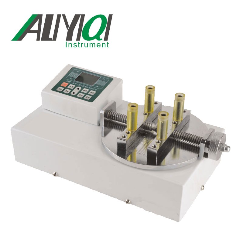
12. 2 sets of installation dimensions, suitable for most test machines at home and abroad, convenient for users to install on the machine;
13. The unique switch contact on-off force test function makes the switch on-off force test more accurate;
14. 6-bit large screen display.
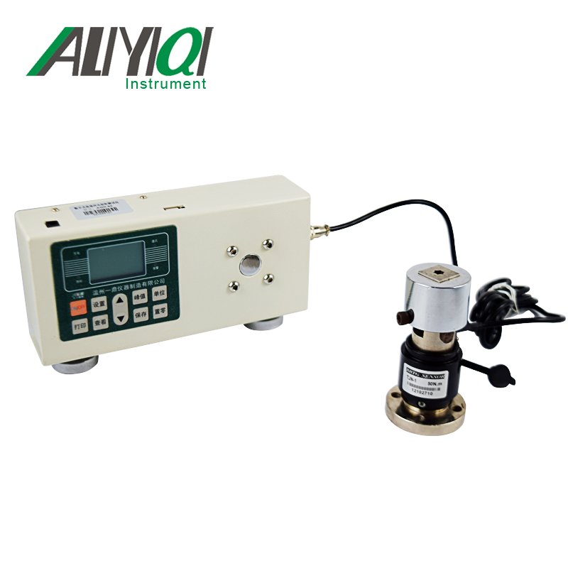
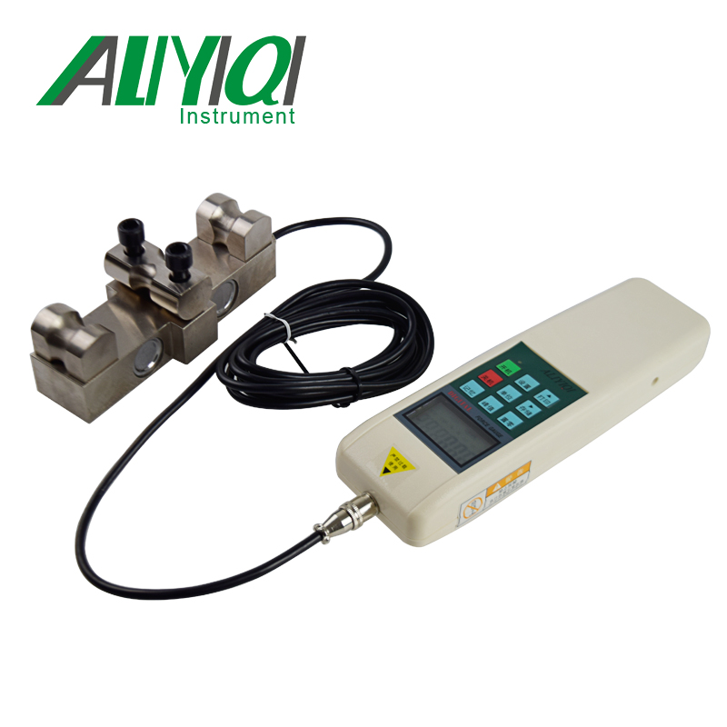
Second, the sensor specifications are shown in Table 1, and the push-pull force gauge model specifications are shown in Table 2.
1. Sensor specification table

2. Model specification table of sensor external push-pull force gauge

3. Safety precautions:
Precautions
Incorrect operation may damage the instrument or cause serious accidents. This manual points out important matters for preventing accidents and how to use the instrument. Please read this manual carefully before use, and keep it properly after reading, so that you can read it again.
If you are testing the impact load, please select the model with the maximum load twice the impact load to be tested;
Warning matters
1. During destructive testing, protective masks and gloves should be worn to prevent the splashing material from hurting the human body during the testing process;
2. Do not use damaged or severely bent fixtures. For self-made fixtures, please refer to the relevant parameters in this manual (the company also has various fixtures, customers can purchase them according to their needs);
3. Do not use the instrument beyond the maximum range. Otherwise, the sensor may be damaged or even an accident may occur;
4. When the test value exceeds 105% of the measuring range, the buzzer will beep continuously. In this case, please quickly release the added load or reduce the load;
Safety Precautions
1. Please use the matching charger to charge, otherwise it will cause circuit failure and even fire;
2. Do not use a power supply other than the rated voltage of the charger, otherwise it may cause electric shock or fire;
3. Do not pull out or insert the plug with wet hands, otherwise it may cause electric shock;
4. Do not pull the plug of the charger's power cord to pull out the plug, so as to avoid the electric cord being broken and being subjected to electric shock;
5. Please clean the machine with a soft cloth. Immerse the cloth in water soaked with detergent, wring it out and remove dust and dirt;
Note: Do not use volatile chemicals to clean the machine (such as volatile agent, thinner, alcohol, etc.)
6. Do not operate the machine in the following environment
(1) Humid environment;
(2) Dusty environment;
(3) Where oil or chemicals are used;
(4) Places with earthquake sources around.
7. Please use and store within the specified temperature and humidity range, otherwise it may cause instrument failure;
8. Do not disassemble, repair or modify the machine by yourself, these actions may cause permanent failure of the instrument;
9. Other matters that need to be paid attention to in safety production.
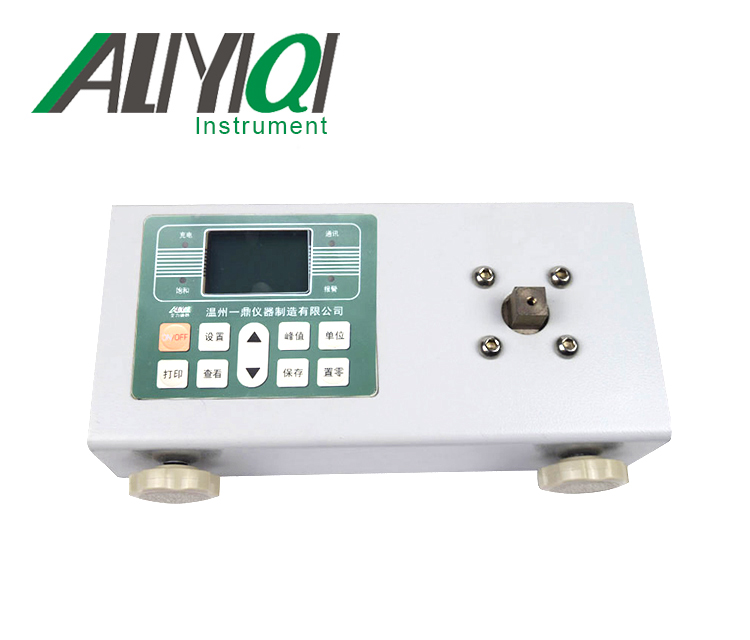
4. Structure name:
1. Structure name diagram

Five, screen display instructions

1. PEAK
When \"PEAK \" is displayed, it indicates Peak mode (peak holding mode), the display shows the peak until manually cleared; when \"AUTO PEAK \" is displayed, it means \"auto peak \" (peak hold automatic release mode) ), The peak value is automatically cleared after 2 seconds; when \"PEAK \" is not displayed, it means \"track mode \" (real-time load value mode), and the value on the screen changes with the load;
2.LO BAT
When the battery voltage drops below 7.0V, \"LO BAT \" appears on the screen, indicating that the voltage is insufficient and needs to be recharged (it can still be tested while charging);
3. MEM
When data is stored in memory, \"MEM \" will be displayed. Press \"DATA \" to check the memory data, MEM \"flashes;
4. In this machine, the thrust (pressure) is displayed as a negative value (\"-\") by default, and the pulling force is a positive value (\"+ \" is not displayed);
5. CMP
Compare function.
This function is activated when the comparison value is set by CPDT (see the corresponding explanation later). \"CMP \" is displayed. The comparison value defaults to full scale, and can be set separately according to needs when used.
6. In the specifications above HF10K, the last digit of the screen \" \"Is the letter \" K \", combined with \" N \", \" kgf \", \" lbf \"to form \" KN (thousand cattle) \", \" t (ton) \", \"Klb (thousand pounds) \" as shown:

Sixth, key description (see picture below)

1. \"Boot \" key
When you press this button, the power is turned on, and the \"power \" indicator will light up (this indicator will also light up when charging), and the model will be displayed. After booting, before you press the\"\" Zero\"button to clear, the zero drift value of the analog signal may be displayed on the screen, just press the\"\"Zero\" button\"to clear;
2. \"Shutdown \" key
Whenever this key is pressed, the power is turned off. But the stored memory data will not disappear;
3. \"Memory \" key
When you press this key, the stored test data (memory data) will be recalled and displayed on the screen in sequence, at this time \"MEM \" flashes-first display the number of memories, automatically display the memory data after 2 seconds. Press \"Peak \" key to exit memory;
4. \"Unit \" key
Press this key to switch the measurement unit, and three units of N (Newton), kg (Kilogram), and lb (Pound) can be displayed cyclically. In the test data display state, the unit conversion of the same value can also be completed. In the specifications above HF10K, it is composed of letters \"K \" \"KN (kilo-newton) \", \"t (ton) \", \"Klb (kilo-pound);
5. \"Peak \" key
Each time you press this key, there will be a switch to display\"PEAK \", display\"AUTO PEAK \", or disappearance of \"PEAK \"-that is, peak hold, peak hold automatic release, and real-time load value switching
6. \"Communication \" key
When the button is pressed in the shutdown state and then the power button is pressed, the stored test data is output to the computer via the data cable and used for communication with the computer. After communication is completed, press \"Peak \" key to shut down.
When \"MODE \" is set, press this key to change the flashing digit between \"0 \" and \"9 \";
7. \"Storage \" key
When you press this key, the test data displayed on the screen will be stored. The stored data can be recalled using the\"\" Memory\"\" key, and can be cleared and cleared using the\"\" Reset\"\" key, and can also be output to the computer for analysis or printing using the\"\" Communication\"\" key.
When the test data is stored in the machine, \"MEM \" is displayed;
8. \"Clear \" key
When this key is pressed, the test value on the screen will be reset to zero.
※ When the weight of the used fixture exceeds 20% of the range or the machine has a load exceeding 20% of the range, press the zero key to reset it. At this time, you need to select a lighter fixture or remove the added load and clear zero;
※ Press and hold this button for 4 seconds, all the stored test data can be cleared (may not be cleared in some states, then restart the machine after shutdown and then execute this function to clear all the memory data).
9. \"Settings \" key
For detailed settings, please refer to the description of various setting methods in \"Function Settings \".
7. MODE function setting:
Press \"Settings \" key in the boot state, at this time there will be set items displayed, the initial display is \"TEST \" ( ), The number setting window appears automatically after 2 seconds. Use the communication key and \"save \" key to set the test mode; then press the \"setup \" key, \"AODT \" (
 ), \"LODT \" (
 ), \"HIDT \" (
 ), \"CPDT \" (
 ), The digital setting windows are automatically displayed after the corresponding items appear for 2 seconds. Use the\"\" Communication\"\" key and \"Storage\" key to set the required parameters. \"Setend \" is displayed, indicating that the setting is completed and the test state is entered.
TEST is represented by four digits, and its specific definition is as follows:
0000 Load real-time value mode 0001 Standard test mode
0002 Push-pull peak mode 0003 Pull peak mode
0004 Thrust peak mode 0005 External node off mode
0006 External node on-off mode
0000 load real-time value (random tracking) mode
Tracking the change of the test load value in any state shows that when the test load value disappears, it returns to zero. At this time, the PEAK function does not work.
0001 Standard test mode (factory default mode)
In this mode, three states can be set, namely real-time load state, peak hold state and automatic peak state. When there is no \"PEAK \" on the display, it is the real-time value state of the load, and the test value changes with the change of the load; press \"Peak \" key, when the word \"PEAK \" is displayed, it is the peak hold state, The displayed test value is the maximum value in the test (regardless of the tension and pressure), which needs to be manually cleared; press the \"Peak \" key again, \"AUTO PEAK \" display, it is the automatic peak state, the displayed test The value is the maximum value in the test (regardless of tension and pressure), and it will automatically disappear after returning to zero for 2 seconds, and the next test can be performed.
0002 Push-pull peak mode-the function of simultaneously grasping the maximum load value in both directions of pressure and tension. When testing the connector, grasp the function of the maximum load (Fc.Ft) of both the positive and negative sides of the insertion force and the extraction force.
※ When the load applied by both the positive and negative sides is greater than the induction value Fa and the load is less than the induction value Fa, only one test (one cycle) is completed (end). Be sure to set the sensing value Fa (perception range).
0003 Peak pull mode-During the plug-in test, only the function of the maximum load (Ft) of the pull-out pull is captured.
0004 Pressure peak mode-only the function of maximum load (Fc) of insertion pressure is grabbed during plug-in test.
0005 0006 Switch contact on-off force test mode-accurately measure the load value at the moment of contact on and off action.
0005 Maximum force value of the external node from disconnection to connection
Connect the two tested contacts to pins 4 and 5 of the data interface (using the data plug in the accessory), press the\"\" peak\"key, select the peak mode, and apply pressure to the switch through the push-pull force gauge until The switch is on. The measured force value at this time is the force value required to turn on the switch.
0006 The maximum value of the external node from on to off
Connect the two tested contacts to pins 4 and 5 of the data interface (using the data plug in the accessory), press the\"\" peak\"key, select the peak mode, and apply pressure to the switch through the push-pull force gauge until When the switch is open, the measured force value at this time is the force value required to open the switch.
The operation load test of the switches and buttons as shown below:
Set in \"PEAK \" state, Fp is the test data value.
After the added load is greater than the set value of Fa, until the contact changes, from off to on or from on to off, the load value of the display will stop changing. The displayed value is the test value.
※ Please connect the PIN4 and PIN5 of the data interface as the contact signal (using the data plug in the accessory).
※ The test cannot be executed without setting Fa (perception range).

AODT sensor value setting
In the simultaneous push-pull test, set the sensing value Fa. Such as: thrust test, if the value exceeds the induction value, it means \"push \" to start the test, and then the value is lower than the induction value, indicating that the thrust test is over; otherwise, the test can be performed in the opposite direction of the pulling force, when the value exceeds the induction value, it means Pull \"to start the test, after which the value is lower than the induction value, indicating that the tensile test is over.
LODT test value lower limit setting
Set the lower limit of the test value, below the lower limit is out of range, \"MIN \" is displayed.
HIDT test value upper limit setting
Set the upper limit of the test value. If the upper limit is exceeded, it is out of range, \"MAX \" is displayed.
CPDT comparison value setting
When the test value exceeds the set comparison value, the buzzer will alarm.
The use of LODT HIDT CPDT enables the instrument to analyze and judge the test data. When the user does not know the debugging, (preferably after powering off and restarting), press and hold the setting key for more than four seconds, release the hand after hearing the sound of\"\",\"the instrument can return to the factory default state, the values are as follows :
TEST: 0001 standard test mode; AODT, LODT: 1% of full scale;
HIDT, CPDT: full scale.
8. Testing
Press \"Power On \" key to turn on the power, and use the factory default settings as needed to directly test or press the Set key to select the test mode and test.
1. Select the appropriate test joint fixture to be installed on the push-pull force gauge (for self-made fixtures, please refer to the relevant data in \"Outline and Installation Dimensions \".
2. Please hold the push-pull force gauge firmly or install the push-pull force gauge on a suitable test machine for testing. During the test, please make the tested force and the push-pull rod of the push-pull force gauge in line to measure the accurate load .
3. After the test is completed, unload the load, turn off the power, remove the fixture, clean each object and put it back in the tool
In the box for the next use.

Nine, storage (memory) data
1. Store data
Only in the peak hold (PEAK) state, after the test is completed, press \"Save \" key, the data will be stored, the display will show \"MEM \", the stored memory data can also be saved after shutdown . When viewing memory data with the\"\" Memory\"\" key, \"MEM \" flashes, the number of memory appears first, and the memory value automatically appears after 2 seconds. Press \"Peak \" to exit the memory and directly enter the test. Data can also be input into a computer for analysis and processing. This machine can store 128 data. When \"O.E \" is displayed, it means that the 129th data can no longer be stored.
2. Memory clear
When the general load is displayed, press the\"\" Zero\"button for more than four seconds, all the memory data will be cleared, and the word\"\"MEM \" will disappear.
This machine can be connected to a computer and input test data into the computer. View and print the test times, average value, maximum value, minimum value, and determine whether the test results meet the set requirements.
10. Change of gravity acceleration value
The user of the machine can input the gravity acceleration value of the use place by himself. Press and hold the \"Peak \" key before powering on, and then press the \"Power On \" key to enter the gravity acceleration value setting interface. After entering the new gravity acceleration value, press \"Settings \" to turn off the system. It can be used after restarting.
11. Calibration method
Please use standard weights regularly to confirm the accuracy of the push-pull gauge. If it is inaccurate, it shall be corrected by the metrology professional according to the following methods:
1. In the shutdown state, long press the\"Memory\" button and long press the power button to start (without load), the display shows \"type \", and a default model is displayed after 2 seconds.
2. Press \"Communication \" key to change the number to the model of the push-pull force gauge, press \"Setting \" key to confirm, display \"sety \" and display 4-digit gravity acceleration value after 2 seconds. Press \"Settings \" again to display 6 digits. After the numbers are stable, press Set to confirm. \"Noload \" is displayed, and 6 digits are displayed again after 2 seconds.
Load the full-scale force value (standard weight) corresponding to this model. After the displayed number is stable, press \"Settings \" to display \"full \", after 2 seconds, display \"setend \" 2 seconds to turn off , The calibration is completed.
12. Other matters needing attention

Thirteen, data interface (9PIN)