I. Instructions for use of the sensor
1. Scope of application:
This series of sensors is a precision measuring instrument that measures various torques, speeds and mechanical power. The application range is very wide, mainly used for:
1. Detection of output torque and power of motor, engine, internal combustion engine and other rotating power equipment;
2. Test of torque and power of fan, water pump, gear box and torque wrench;
3. Testing of torque and power in railway locomotives, automobiles, tractors, airplanes, ships, mining machinery;
4. It can be used for torque and power detection in sewage treatment system;
5. Can be used to manufacture viscometer;
6. Can be used in process industry and process industry.
2. Packing inspection
After unpacking, please carefully count the items listed in the \"Packing List\", confirm whether the items in the box are consistent with the \"Packing List\", check whether the items are damaged during transportation, and check the nameplate of the shipped product. Confirm that the product model, specifications and parameters are consistent with your order requirements. If you have any questions, please contact our company immediately.
Note: For special customized products, the items in the box are subject to the items listed in the \"Packing List\".
Items in the box:
①Torque power meter ②Sensor
③Instruction manual ④Qualification certificate
⑤ Verification report
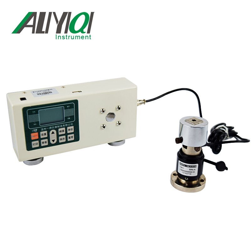
3. The basic principle of torque measurement
Torque measurement: The strain gauge electrical measurement technology is used to form a strain bridge on the elastic shaft. The electrical signal of the elastic shaft torsion can be measured by supplying power to the strain bridge. After the strain signal is amplified, it is subjected to pressure / frequency conversion. Becomes a frequency signal proportional to the torsion. as the picture shows:

Fourth, the basic principle of speed measurement
Rotational speed measurement: The magnetoelectric code disk is used for measurement. Each magnetoelectric code disk has 60-180 (optional) teeth. The shaft drives the magnetoelectric code disk to produce 60-180 (optional) pulses per revolution, high speed Or in the medium speed sampling, the frequency measurement method can be used, and in the low speed sampling, the accurate rotation speed can be measured by the period measurement method. Speed measurement can be up to 15000rpm. The accuracy of this sensor can reach ± 0.1% ~ ± 0.5% (F · S). Because the sensor output is a frequency signal, it can be sent directly to a computer for data processing without AD conversion.
The speed measurement method of this sensor adopts built-in speed measurement, the user needs to indicate whether to monitor the speed signal when ordering.
5. Product features:
1. The square wave amplitude of the signal output waveform can be selected from 5V / 12V / 15V / 24V.
2. You can enter the working state within 5 minutes of starting up without preheating process.
3. High detection accuracy, good stability and strong anti-interference.
4. The forward and reverse torque can be measured continuously without repeated zero adjustment.
5. Small size, light weight, easy to install.
6. The sensor can be used independently from the secondary instrument. As long as the power supply of ± 15V (200mA) is provided according to the pin number of the socket, the frequency signal of equal square wave or pulse wave with impedance proportional to torque can be output.

6. Main performance and electrical indicators:
|
Torque accuracy |
<± 0.5% F · S, <± 0.3% F · S, <± 0.1% F · S (optional) |
|
Frequency response |
100μs |
|
Nonlinear |
< ± 0.1% F · S |
|
Repeatability |
< ± 0.1% F · S |
|
Backlash |
< 0.1% F · S |
|
Zero drift |
< 0.2% F · S / year |
|
Zero temperature drift |
500MΩ |
|
Static overload |
120% 150% 200% (optional) |
|
Operating temperature |
-10 ~ 50 ℃ (-50 ~ 95 ℃ optional) |
|
Storage temperature |
-20 ~ 70 ℃ |
|
voltage |
± 15V ± 5% or 24VDC |
|
Total current consumption |
< 200mA |
|
Frequency signal output |
5KHZ ~ 15KHZ (0 ~ 5V / 1 ~ 5V / 0 ~ 10V / 4 ~ 20mA optional) |
|
Speed signal output |
60 pulses / rev (0 ~ 5V / 0 ~ 10V / 4 ~ 20mA optional) |
|
Rated torque |
10KHZ ± 5kHZ (positive and negative bidirectional measured value), |
|
Signal duty cycle |
(50 ± 10)% |
Seven, size comparison table

|
specification (N.M) |
Φ D |
Φd |
L |
E |
H |
h |
B |
G |
F |
Key (length × width × height) |
Remarks |
weight |
|
5-100 |
92 |
18 |
188 |
30 |
128 |
57 |
65 |
8 |
79 |
30 × 6 × 6 |
single bond |
6Kg |
|
500 |
96 |
33 |
229 |
47 |
133 |
60 |
65 |
8 |
79 |
45 × 10 × 8 |
single bond |
7.5Kg |
|
1K-2K |
124 |
45 |
306 |
70 |
172 |
85 |
65 |
8 |
100 |
55 × 14 × 9 |
Single / double bond |
16Kg |
|
5K |
160 |
70 |
354 |
90 |
205 |
100 |
100 |
11 |
120 |
90 × 20 × 12 |
Double bond |
25Kg |
|
10K |
160 |
70 |
395 |
98 |
205 |
100 |
100 |
11 |
120 |
90 × 20 × 12 |
Double bond |
26Kg |
|
20K |
206 |
115 |
420 |
125 |
248 |
120 |
65 |
14 |
200 |
115 × 32 × 18 |
Double bond |
80Kg |
|
50K |
250 |
140 |
460 |
140 |
293 |
143 |
65 |
14 |
230 |
138 × 36 × 20 |
Double bond |
100Kg |
|
100K |
350 |
180 |
550 |
150 |
400 |
200 |
110 |
20 |
280 |
150 × 45 × 25 |
Double bond |
150Kg |
8. Electrical connection:
As shown in the figure, the torque sensor is connected to external equipment with an aviation connector (P12-7AB) connector, and the socket end is fixed on the chassis.

1. (Black) G 2. (Red) Power supply is positive
3. (Brown) negative power supply 4. (White) speed signal
5. (Yellow) Torque signal 6. Shield
7. Empty
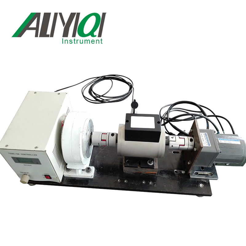
Nine, installation diagram
The schematic diagram of horizontal installation:

10. Installation method and precautions
1. Measure the shaft diameter and center height of the sensor first, to be installed.
2. Use two sets of couplings to install the sensor between the power equipment and the load.
3. It is recommended to use flexible universal joint coupling for installation, and the concentricity is guaranteed to be less than 0.03mm.
4. Adjust the center height and coaxiality of the power equipment, load, and sensor respectively, and then fix it, and fasten it reliably, without loosening.
5. The installation base should have a certain strength.
6. The coupling should be close to the shaft shoulders at both ends of the sensor.
7. After all installations are completed and confirmed to be correct, the power can be debugged.
pay attention
◆ Positive positive and negative torques: Fix one end of the shaft and apply a torque clockwise at the other end to determine positive torque; otherwise, negative torque The installation of the sensor must be installed by a professional mechanical installer.
◆ Environmental requirements for installation:
① Temperature: -10 ℃ ~ 60 ℃ ② Humidity: <90% RH ③ No flammable or explosive materials
◆ Do not directly knock or bump the sensor during installation.
◆ Live operation is prohibited during installation.
◆ This sensor is non-waterproof and explosion-proof, so please pay attention when using it.
◆ Avoid strong interference and ensure the normal operation of the instrument.
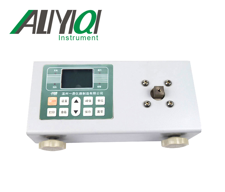
Ⅱ. Instructions for use of the instrument
11. Basic Technical Specifications
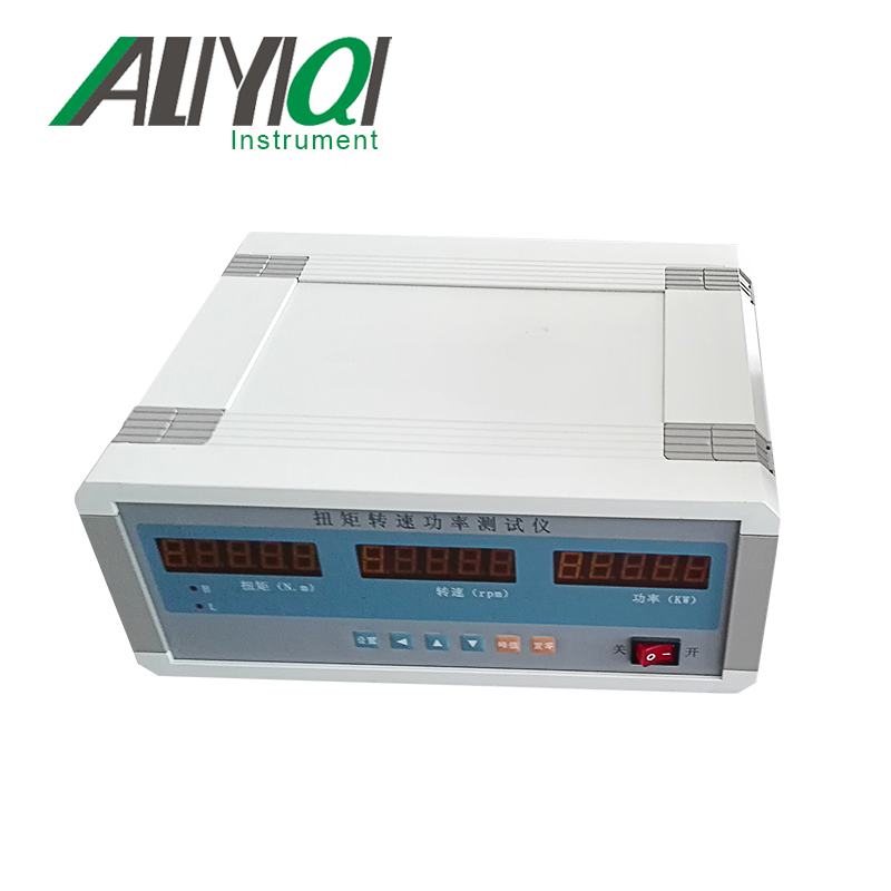
● Size: appearance 270 × 106 × 220mm.
● Instrument power supply: 220VAC.
● Display range: Torque measurement: -99999 ~ 99999N.m, the display takes absolute value: 0 ~ 99999N.m, the decimal point position can be set.
Speed display: 0 ~ 99999, the decimal point position can be set.
Power display: 0 ~ 99999, decimal point is automatically adjusted.
● Pulse input signal: various NPN, PNP, OC gate output sensor signal, proximity switch, rotary encoder.
● Transmit output:
◎ Photoelectric isolation.
◎ 2 channels of 4mA ~ 20mA DC current output. Output resolution: 1/4000; error is less than ± 0.2% F.S, load capacity: less than or equal to 600Ω.
◎ External power supply: ± 15VDC or 24VDC, choose one of the two.
● Measurement frequency: speed pulse input 1Hz ~ 20KHz.
Torque pulse input 5KHz ~ 15KHz, can be extended to 1HZ ~ 60KHZ.
12. Panel and key description

|
Name |
Explanation |
||
|
显 示 窗 |
① First display window of measured value |
· The torque measurement value is displayed. · In the parameter setting state, the parameter symbol and parameter value are displayed. · The last decimal point flashes to indicate the peak display status. |
|
|
② Second display window of measured value |
· The measured speed value is displayed. · It is not displayed in the parameter setting state. |
||
|
③ Third display window of measured value |
· Display value power measurement. · It is not displayed in the parameter setting state. |
||
|
④ Indicator |
· Alarm status of the torque alarm point and display of peak sign. |
||
|
操 作 键 |
\"Settings \" key |
· In the measurement state, press and hold for more than 2 seconds to enter the setting state. · In the setting state, press once to display the next parameter and store the previous parameter at the same time. |
|
|
\" Shift key |
· It is invalid in the measurement state. · In the setting state: ① Call up the original parameter value. ② Move the modification bit. |
||
|
\" Increase key |
· It is invalid in the measurement state. · In the setting state, increase the parameter value or change the setting type. |
||
|
\" Decrease key |
· It is invalid in the measurement state. · In the setting state, reduce the parameter value or change the setting type. |
||
Thirteen, instrument parameter description
|
name |
content |
Ranges |
Explanation |
|
OA |
Password 1 |
0 ~ 99999 |
|
|
OA1 |
Password 2 |
0 ~ 99999 |
|
|
FLtr |
Filter coefficient |
0 ~ 72 |
|
|
in-d |
Decimal point position of torque display |
0 ~ 4 |
|
|
Lc |
Torque range (absolute value) |
256 ~ 99999 |
|
|
AH |
Torque alarm 1 |
0 ~ 99999 |
|
|
AL |
Torque alarm 2 |
0 ~ 99999 |
|
|
in-d1 |
Speed decimal point position |
0 ~ 1 |
|
|
Lc1 |
Speed transmission range |
0 ~ 10000 |
|
|
PULSE |
Pulses per revolution |
1 ~ 2000 |
|
|
t-y |
Clock \"Year \" Settings |
00 ~ 99 |
Adjust when the clock is inaccurate |
|
t-n |
Clock \"Month \" Settings |
1 ~ 12 |
Adjust when the clock is inaccurate |
|
t-d |
Clock \"Day \" setting |
1 ~ 31 |
Adjust when the clock is inaccurate |
|
t-H |
Clock \"hour \" setting |
0 ~ 23 |
Adjust when the clock is inaccurate |
|
t-F |
Clock \"minute \" setting |
0 ~ 59 |
Adjust when the clock is inaccurate |
14. Instrument Operation Instructions
1. Hold down the setting key \"Settings \" for more than 2 seconds and do not release it to enter the setting state.
2. The\"Settings\" key can select other parameters of this group in sequence:
press\" \"Key to call up the original setting value of the current parameter, the flashing bit is the correction bit.
by\"\"Move to modify the position, \" \"Key value-added, \"
 \"Key decrement, modify the parameter to the required value.
3. Press \"Settings \" to save the modified parameters and go to the next parameter. If it is the last parameter of this group, press \"Setting \" key to exit the setting state, repeat steps ② ~ ⑤ to set other parameters.
Fifteen, functional operation:
1. The torque value is cleared: Press and hold the\"\" Zero\"button and do not release it until the torque is displayed as zero. This function is used to clear the zero drift of the sensor to achieve the best detection effect.
2. Peak torque display: Press the \"Peak \" key, the peak value is displayed in the torque display window. When the peak value is displayed, the number at the end flashes. Press the \"Peak \" key again, and the torque window will return to the real-time torque measurement value. The peak value returns to zero after the torque zeroing operation has been performed, or after a power failure.
16. Wiring Instructions

17. Schematic diagram of the external dimensions of the instrument
270mm (length) x106mm (height) x220mm (deep)
Suggestion: Wiring space of the rear terminal extending 100mm backward


18. Communication function
1. Data format: The data format is 10 bits: 1 start bit, 8 data bits, no parity bit, 1 stop bit.
2. Baud rate: fixed at 9600bps.
3. The communication address of the instrument: fixed to 01, (if there are special requirements, please indicate when ordering).
● All commands sent and received by the instrument are ASCII codes. For the ASCII codes of common symbols, see the appendix ASCII table.
● The meter automatically recognizes whether the command has a check core. If the command sent by the host is with a check core, the meter will also reply with a check core. It is recommended that all data transmitted should have a check core, which can prevent errors The data is received, improving the overall stability of the system.
● About the verification core:
Features:
The check core helps to detect command errors from the computer to the meter and to detect wrong answers from the meter to the computer. The check core function adds 2 characters to the command and answer strings without affecting the transmission rate.
Set up:
Whether to use the verification core does not need to be set for the instrument, the instrument automatically determines whether the command issued by the computer contains the verification core. If the command contains a check core, the instrument automatically adds a 2 character check core when answering. This means that the computer can use a check core for certain instruments or certain commands in the network in a targeted manner.
format:
The verification core ranges from 00 to FFH, which is represented by 2 digits of 40H to 4FH ASCII code, and is sent before the end character of command or answer \"¿\" (0D). If the verification core in the command issued by the computer is incorrect, the meter will not answer.
Calculation:
1. The check core of the command is equal to the sum of all command ASC II code values. The remainder is retained when it exceeds the range.
2. The verification core of the answer is equal to the sum of the ASC II code values of all the answers plus the ASC II code value of the address of this instrument. The remainder is retained when it exceeds the range. Example description: sending and receiving format and calculation method of check core.
Example: This command: # 0102NF¿
(Ie send hexadecimal to the meter: 23 30 31 30 32 4E 46 0D)
Answer: = + 123.5LB¿
(That is, the instrument sends out hexadecimal: 3D 2B 31 32 33 2E 35 4C 42 0D)
The verification core of the sent command string is calculated as follows:
Verification core = 23H + 30H + 31H + 30H + 32H = E6H
#, 0, 1, 0, 2 ASC Ⅱ codes are 23H, 30H, 31H, 30H, 32H The sum of these ASC Ⅱ codes is E6H, using two 40 ~ 4FH ASC Ⅱ codes as 4EH, 46H, namely N, F .
The verification core of the answer string is calculated as follows (the two ASCII codes after sending the delimiter are the address of the instrument):
Verification core = 3DH + 2BH + 31H + 32H + 33H + 2EH + 35H + 41H + 30H + 31H
= 1C2H
=, +, 1, 2, 3, ·, 5 ASCII codes are 3DH, 2BH, 31H, 32H, 33H, 2EH, 35H and the sum of these ASCII codes plus the ASCII code 30H of the instrument address, 31H is 1C2H, The remainder is C2H, which is expressed as 4CH, 42H, that is, L and B, using the two-digit ASCII code of 40 ~ 4FH.
Command 1: # 0100↙
Command for reading torque value. (Answers start with \"= \" and end with carriage return)
Command 2: # 0101↙
It is a command to read the speed value. (Answers start with \"= \" and end with carriage return)
Command 3: # 0102↙
Read power value command. (Answers start with \"= \" and end with carriage return)
All command characters are transmitted in ASCII code.
Appendix: Commonly used ASCII codes in communication
|
Hex |
ASCⅡ |
Hex |
ASCⅡ |
Hex |
ASCⅡ |
||
|
20 |
Space |
37 |
7 |
49 |
I |
||
|
21 |
! |
38 |
8 |
4A |
J |
||
|
22 |
" |
39 |
9 |
4B |
K |
||
|
23 |
# |
3A |
: |
4C |
L |
||
|
24 |
$ |
3B |
; |
4D |
M |
||
|
25 |
% |
3C |
< |
4E |
N |
||
|
26 |
& |
3D |
= |
4F |
O |
||
|
27 |
' |
3E |
> |
50 |
P |
||
|
2B |
+ |
3F |
? |
51 |
Q |
||
|
2D |
- |
40 |
@ |
52 |
R |
||
|
2E |
· |
41 |
A |
53 |
S |
||
|
30 |
0 |
42 |
B |
54 |
T |
||
|
31 |
1 |
43 |
C |
55 |
U |
||
|
32 |
2 |
44 |
D |
56 |
V |
||
|
33 |
3 |
45 |
E |
57 |
W |
||
|
34 |
4 |
46 |
F |
58 |
X |
||
|
35 |
5 |
47 |
G |
59 |
Y |
||
|
36 |
6 |
48 |
H |
5A |
Z |
Ⅲ 、 Magnetic powder brake
Nineteenth, shaft coupling, machine support magnetic powder brake (this product is optional)
When the rated torque is greater than 400N · m, the rated voltage is DC36V and the remaining rated voltage is DC24V.
|
specification model |
Rated Torque N · m |
Slip power Kw |
excitation Electric current A |
Allow Rotating speed r / min |
Dimensions |
Shaft coupling size |
Frame support size |
cool down the way |
|||||||||
|
H |
L |
d ( h7) |
b ( p7) |
L1 |
L2 |
L3 |
L4 |
L5 |
L6 |
H1 |
d1 |
Natural cold |
|||||
|
FZ2.5.J |
2.5 |
0.1 |
0.4 |
1500 |
110 |
85 |
10 |
3 |
20 |
6 |
50 |
68 |
100 |
120 |
60 |
7 |
Natural cold |
|
FZ5.J |
5 |
0.3 |
0.5 |
1500 |
138 |
94 |
12 |
4 |
25 |
10 |
50 |
68 |
120 |
140 |
75 |
7 |
Natural cold |
|
FZ10.J |
10 |
0.8 |
0.6 |
1500 |
166 |
96 |
14 |
5 |
25 |
6 |
60 |
85 |
120 |
150 |
90 |
10 |
Natural cold |
|
FZ25.J |
25 |
2 |
0.8 |
1500 |
196 |
109 |
20 |
6 |
36 |
8 |
70 |
96 |
150 |
180 |
110 |
12 |
Natural cold |
|
FZ50.J / Y |
50 |
4 |
1 |
1500 |
240 |
133 |
25 |
8 |
42 |
11 |
80 |
105 |
180 |
210 |
130 |
12 |
Single water cooling |
|
FZ100.J / Y |
100 |
7 |
1.2 |
1500 |
284 |
233 |
30 |
8 |
58 |
14 |
100 |
130 |
250 |
290 |
155 |
12 |
Double water cooling |
|
FZ200.J / Y |
200 |
10 |
1.8 |
1000 |
329 |
244 |
35 |
10 |
58 |
12 |
120 |
165 |
280 |
330 |
180 |
15 |
Double water cooling |
|
FZ400.J / Y |
400 |
12 |
2.5 |
1000 |
400 |
298 |
45 |
14 |
82 |
22 |
130 |
180 |
330 |
390 |
215 |
15 |
Double water cooling |
|
FZ630.J / Y |
630 |
15 |
2.5 |
750 |
441 |
353 |
60 |
18 |
105 |
20 |
150 |
210 |
410 |
480 |
240 |
19 |
Double water cooling |
|
FZ1000.J / Y |
1000 |
20 |
2.5 |
750 |
523 |
390 |
70 |
20 |
105 |
35 |
160 |
210 |
470 |
540 |
280 |
19 |
Double water cooling |
|
FZ2000.J / Y |
2000 |
30 |
3 |
450 |
619 |
468 |
80 |
22 |
130 |
54 |
170 |
240 |
580 |
660 |
330 |
24 |
Double water cooling |
|
FZ5000.J / Y |
5000 |
50 |
3 |
300 |
824 |
566 |
90 |
25 |
140 |
13 |
320 |
388 |
600 |
700 |
430 |
24 |
Double water cooling |
|
FZ10000.J / Y |
10000 |
60 |
4 |
250 |
1126 |
611 |
120 |
32 |
160 |
18 |
360 |
450 |
900 |
1030 |
600 |
28 |
Double water cooling |
|
FZ20000.J / Y |
20000 |
75 |
5 |
200 |
1620 |
850 |
155 |
40 |
180 |
105 |
400 |
550 |
1300 |
1450 |
750 |
34 |
Double water cooling |