I. Overview
1.1 Main uses and scope of application
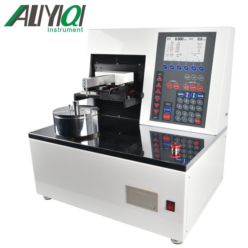
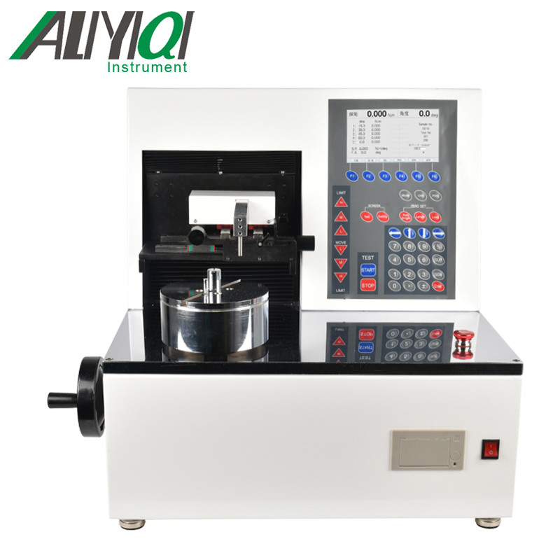
The ANSM automatic torsion spring testing machine is made according to the technical requirements stipulated in the national standard JB / T7796-2005. This instrument is mainly used for torsion-angle and angle-torque testing of various springs. It is a high-performance testing machine that can exert high-efficiency and labor-saving spring detection functions. It is widely used in spring manufacturing companies and various scientific research place.
1.2 Product features
1.2.1 1,2,3,4,5 section load (angle) spring constant number automatic test, free angle measurement can be easily completed.
1.2.2 The automatic origin correction function completes the calculation and compensation of the load cell and machine material rigid structure deformation to ensure high-precision measurement.
1.2.3 Touch-screen man-machine conversational test condition setting input is more convenient and fast.
1.2.4 To facilitate the calculation and input of tolerances, after entering the tolerance percentage value, the system will automatically calculate the upper and lower limits.
1.2.5 As many as ten kinds of test types can not only meet the production measurement, but also meet the test of spring engineering design requirements.
1.2.6 Test load units are N.m, Kg.cm, Lb.in.
1.2.7 For easy operation, the measurement range can be freely converted into 5 test ranges.
1.2.8 Automatically correct the position of the load test plug gauge and rotary plug gauge through the turntable to obtain an accurate zero position.
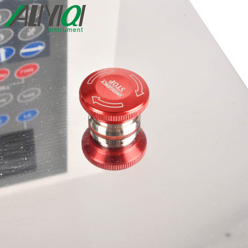
1.2.9 The system is equipped with overload protection and emergency stop functions.
1.2.10 The system can be set to repeat the number of cycles for automatic testing by a simple operation.
1.2.11 With data printing function.
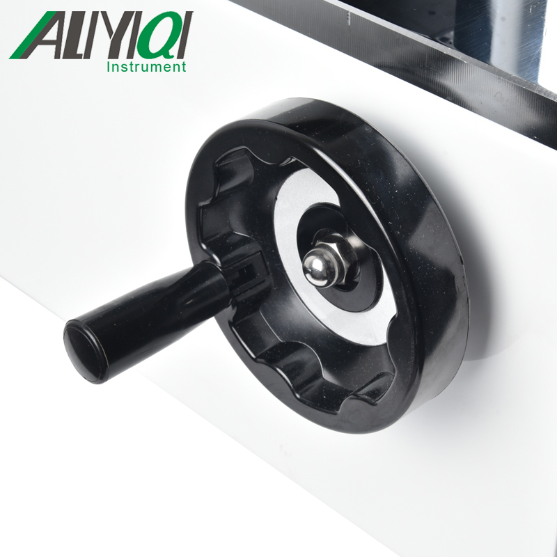
1.2.12 Rotary displacement control button, with 10 degrees, 1 degrees, and 0.1 degrees slow-motion rotation level, can accurately control the angle.
1.3 Specification parameter table
|
model |
ANSM-1 |
ANSM-3 |
ANSM-5 |
ANSM-10 |
ANSM-20 |
|
MAX torque (N.m) |
1 |
3 |
5 |
10 |
20 |
|
MIN torque display value |
0.0001 |
0.0001 |
0.0001 |
0.0001 |
0.001 |
|
unit |
N.m, Kg.cm, Lb.in |
||||
|
Test speed |
1-1800deg / min |
||||
|
Manual rotation angle selection |
|||||
|
Test product diameter |
|||||
|
Test angle |
7200deg |
||||
|
turn around |
|||||
|
power supply |
AC 220V (110AC) |
||||
|
Dimensions (mm) |
697 * 450 * 623 |
||||
|
Weight (Kg) |
120 |
||||
Second, the overall product structure
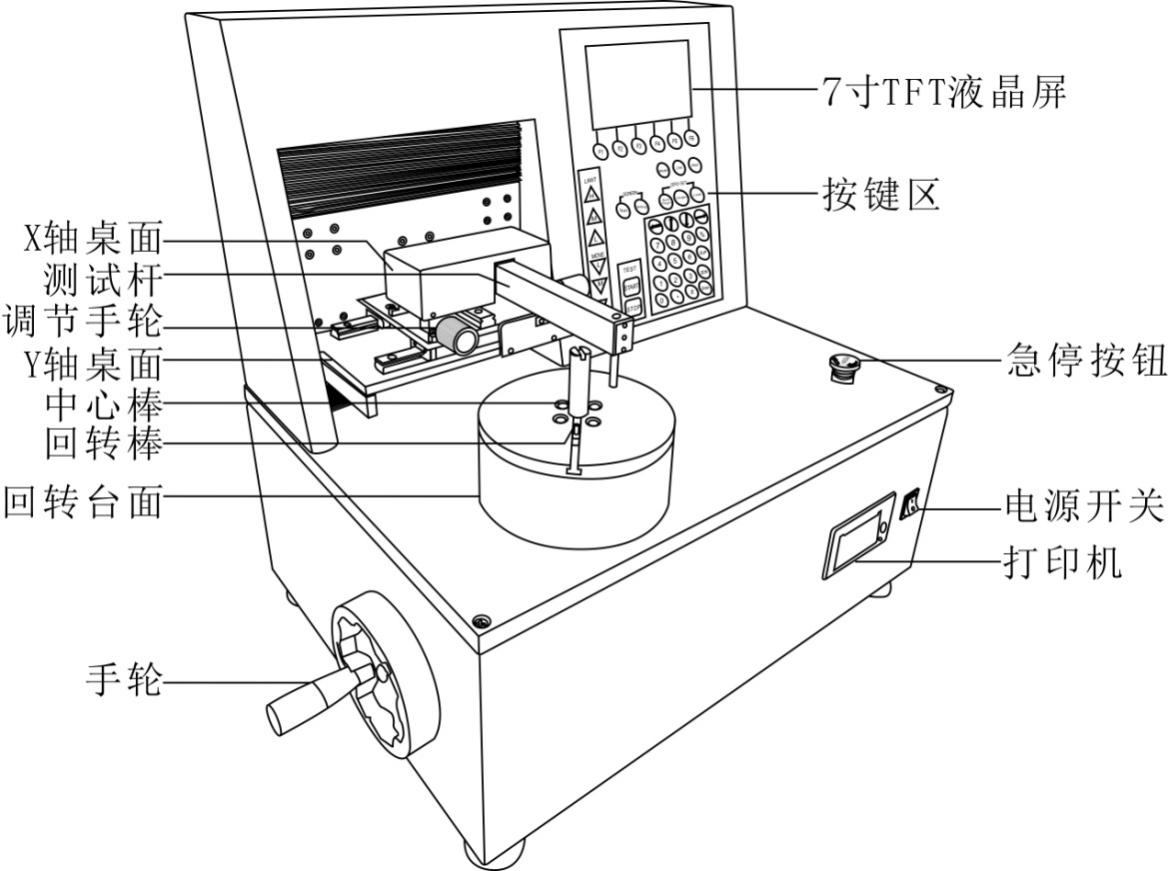
2.1 Overall structure
2.2 Key functions
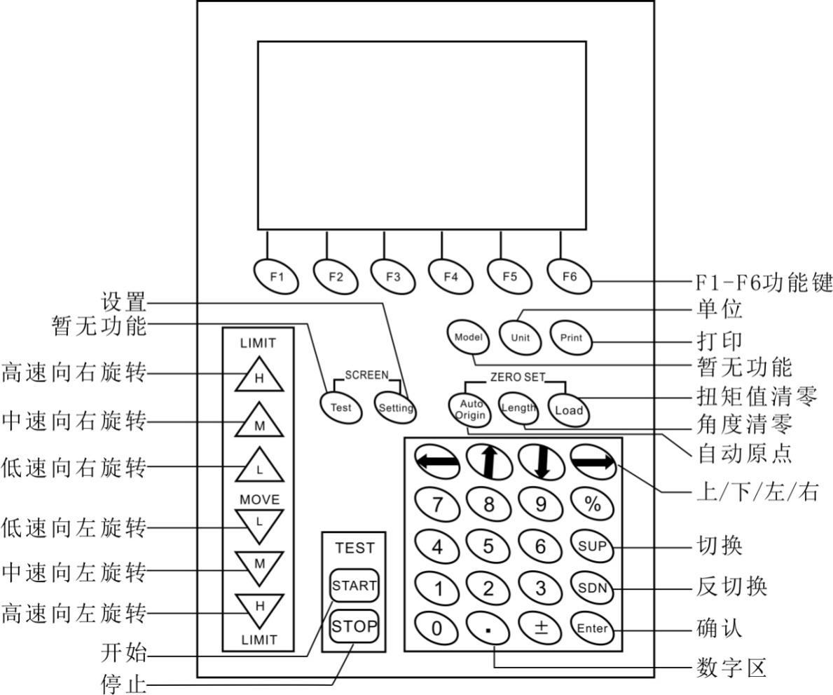
2.2.1 Function keys: The six function keys F1 ~ F6 are common to all the interface of the instrument, and correspond to the keys at the bottom of the screen after power on.
2.2.2 High-speed / medium-speed / low-speed rotation to the right, high-speed / medium-speed / low-speed rotation to the left: these 6 keys have two functions of short press and long press,
Short press the single step angle adjustment for the rotary table, the user can manually adjust the angle of the rotary table according to their own requirements. For example, short press the high-speed right-hand turntable to the right to run 10deg at a higher speed, the medium-speed right-hand turntable to the right to run at a middle speed of 1deg, and the low-speed right-hand turntable to the right at a low speed of 0.1deg.
If you press these buttons for about 4 seconds, you can make the rotary table run up or down at a certain speed until the stop button is pressed or the protection mechanism is activated. The high, medium and low speeds correspond to 100deg / min, 50deg / min and 10deg / min respectively.
2.2.3 Unit key: Unit switching.
2.2.4 Print key: It is effective in the real-time measurement interface and data saving display interface. Short press the print key in the real-time measurement interface to print the currently displayed segment data; There are two printing methods in the data saving display interface, one is to print the current A small group of data can also print a set of all repeated measurement data.
2.2.5 Setting key: Short press this key to enter the system setting interface.
2.2.6 Automatic origin: Short press this key, the spring will return to the free state and record the free angle.
2.2.7 Angle reset: Short press this key to reset the angle display.
2.2.8 Clear torque value: Press this key briefly to clear the torque value. The torque value reset must be effective when the motor is stopped.
2.2.9 Start key: short press this key to start the test.
2.2.10 Stop button: Short press this button to terminate the test.
2.2.11 Up / Down / Left / Right key: Used to select the number of digits when setting the spring.
2.2.12 Numeric keys: used for spring setting.
2.2.13 Switch / reverse switch / confirm key: used to select and confirm the controls in the interface.
3. Use and operation
3.1 Measurement interface
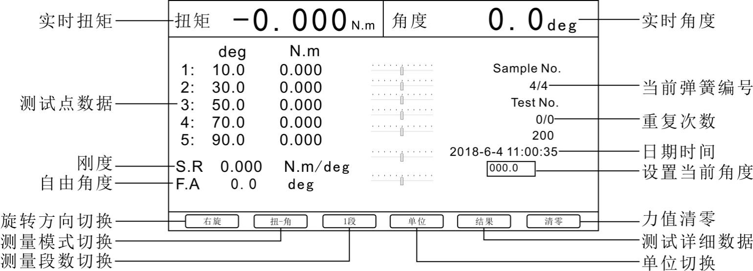
a. The real-time measurement interface mainly displays the real-time torque and angle of the current test; if during the test, the data of the test point is recorded, and the current spring number and the number of repetitions are also displayed.
b. In the real-time measurement interface, you can switch the direction of spring rotation, measurement mode, number of measurement segments and units; after the switch, the system will save the corresponding settings.
c. Rotation direction switching: control the turntable to rotate left or right.
d. Switching of measurement mode: it is divided into torsion-angle and angle-torsion. The difference between these two modes is that the reference is different. Torsion-angle is to record the spring torque according to the corresponding angle; angle-torsion is to record the spring according to the corresponding torque Angle.
e. Number of measuring segments: According to the set number of measuring segments, test the corresponding spring test points. One segment is to find the angle or torque of the first test point.
Real-time spring measurement, depending on the type, and the selected angle (relative to absolute) mode. The setting value of its running measurement will also be different.
In the twist-angle mode, select the angle relative mode, then the reference angle of segment 1 to segment 5 needs to be increased, otherwise it will not work properly; if the angle absolute mode is selected, then the reference angle of segment 1 to segment 5 It is decreasing, otherwise it will not work properly.
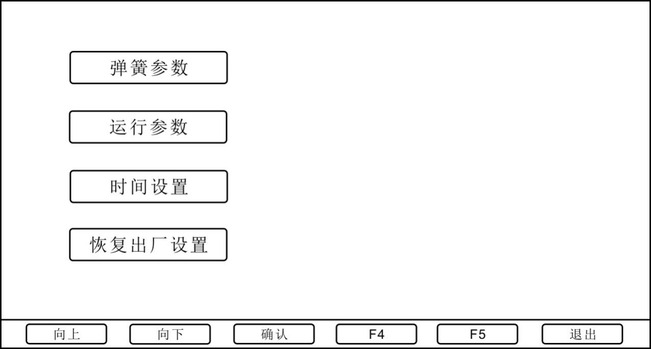
3.2 System settings
System settings include spring parameter settings, operating parameters, time settings, and factory reset. As shown below:
3.2.1 Spring setting
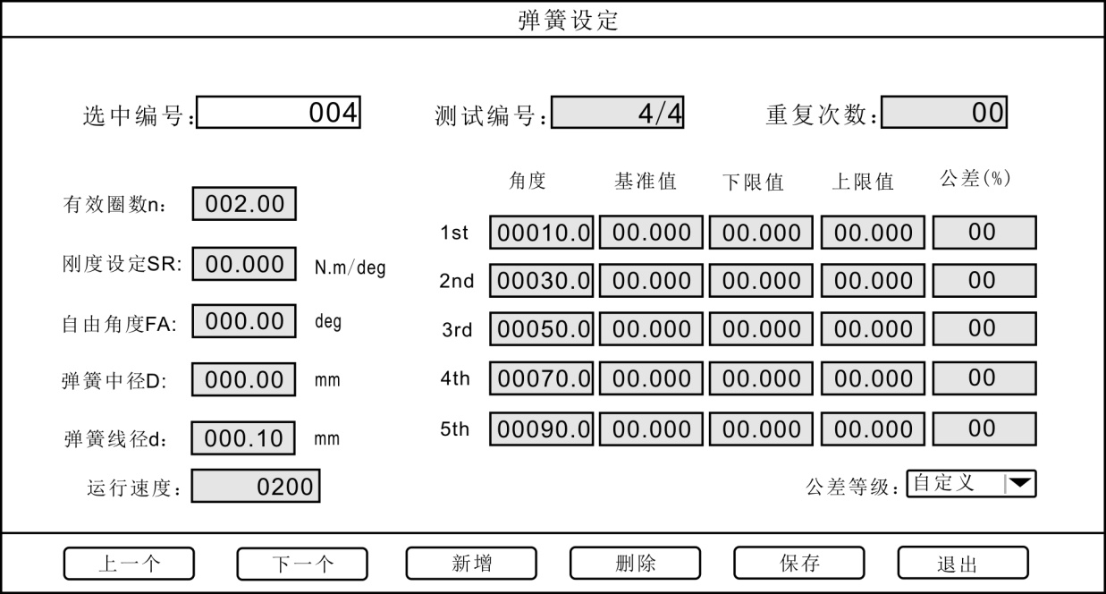
a. Test number: The test number MAX can be set to \"32 \". After pressing \"Add \", the test number increases by one group, enter the required spring parameters, and press \"Save \". As shown below:
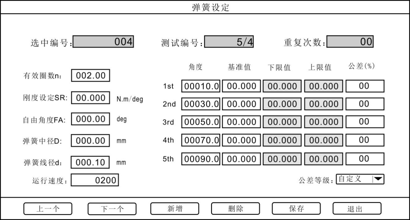
b. Number of repetitions: The number of repetitions MAX can be set to \"99 \". After pressing \"Add \", the test number increases by one group. Press \"SUP \" and \"SDN \", and the cursor moves to \" At the number of repetitions \, enter the required value and press \"Save \".
c. Running speed: The running speed during the spring test is expressed as mm / min. The larger the value, the faster the speed.
d. Angle (deg): the position of the spring test period.
e. Reference value: the force value corresponding to the segment point.
f. Tolerance: The setting for determining the qualified range of the spring can be set from \"0% \" to \"99% \". For example, when set to \"1% \", the upper limit value is and the lower limit value is. During the spring test, if the force value is within the upper and lower limits, it is qualified.
After setting the spring parameters, press \"Save \". Users can also switch \"selected number \" to choose different spring settings.
3.2.2 Operating parameters
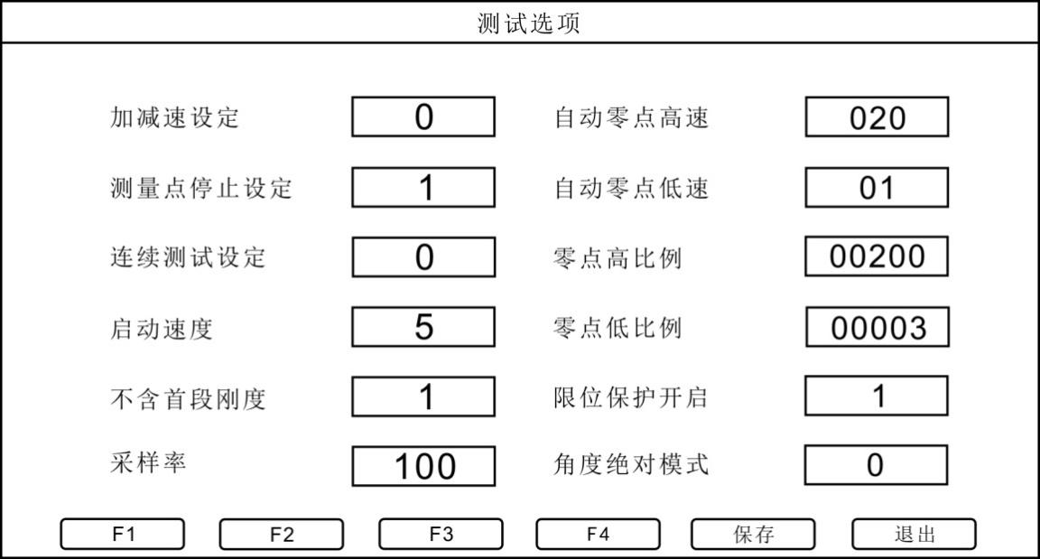
a. Acceleration and deceleration setting: acceleration and deceleration setting refers to the acceleration setting of the rotary table during measurement. When set to \"0 \", it is turned off; when set to \"1 \", it is turned on. The acceleration setting and the measurement point stop setting are in conflict. Only when the measurement point stop setting is set to \"0 \", the acceleration / deceleration setting is valid.
b. Measurement point stop setting: The measurement point stop setting refers to the stop setting of the instrument at each segment point during measurement. When it is set to \"0 \", it is turned off; when set to \"1 \", it is turned on. status. In the open state, if the segment number is set to \"5 \", the instrument will stop once at these five segment points during measurement; if it is off, the instrument will not stop at the segment point during measurement.
c. Continuous test setting: Repeat the test setting. When set to \"0 \", it is turned off; when set to \"1 \", it is turned on.
d. Starting speed: The starting speed setting is only valid when the acceleration / deceleration setting is turned on. The starting speed can be set from \"1 \" to \"5 \". When set to \"1 \", that is, the acceleration from 1mm / min to 100mm / min during measurement, the greater the value setting, the faster the acceleration start speed. The speed setting unit is mm / min, and the starting speed cannot be set to \"0 \".
e. Excluding the stiffness of the first segment: When the stiffness of the first segment is set to \"1 \", it is turned on. For example, when 5 segments are set, the instrument will not calculate the stiffness of the first segment when calculating the average stiffness. If it becomes \"0 \", it is closed.
f. Sampling rate: the sampling times of the instrument per second, which can be set from \"1 \" to \"100 \".
g. Automatic zero speed:High-speed setting of automatic origin, the unit is \"mm / min \". When the automatic origin button is pressed during measurement, the spring will return to a position relatively close to the origin with the set automatic zero high-speed value.
h. Automatic zero low speed:Auto zero low speed is a value set on the basis of auto zero high speed, the unit is \"mm / min\". When the spring returns to a position relatively close to the origin, the automatic zero point starts at a low speed at this time, so that the spring returns to the origin position more accurately.
i,Zero point high ratio / zero point low ratio: These two parameters are the force value determination of the automatic origin. The ratio of zero point height is \"200 \", that is, the force value is full scale * 200/10000, which is 2% of full scale. The low ratio of zero point is \"3 \", that is, the force value is full scale * 3/10000, which is 0.03% of full scale. After starting the automatic origin, when the force value is close to 2% of the full scale, the instrument will stop at the position of the automatic origin according to the low percentage of the force value after the force value pauses for a few seconds.
j. Angle absolute mode: when set to \"1 \", it is angle absolute mode; when set to \"0 \", it is relative displacement mode. For relative measurement mode and absolute measurement mode is the difference between the set angle. The relative measurement mode is how much the angle is rotated, and the absolute measurement mode is expressed as how much the angle is rotated.
Relative measurement mode, the angle required to set the number of spring segments, ANGLE1 < ANGLE2 < ... < ANGLE5
At the same time, torque setting is also required, TORQUE1 < TORQUE2 < ... < TORQUE5
The absolute measurement mode will have different setting parameters for different spring types
ANGLE1 > ANGLE2 > ... > ANGLE5
3.2.3 Time setting
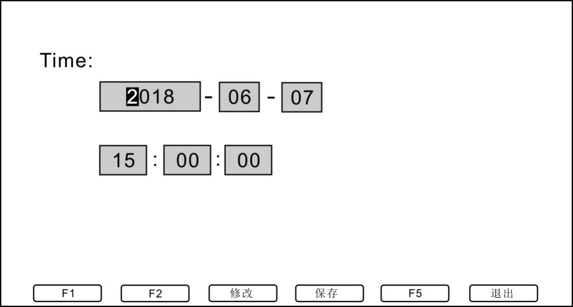
Time setting is used to set the time displayed on the measurement interface and the printing time.
3.2.4 Restore factory settings
Press this key to restore the instrument to factory settings and restart automatically.
3.3 Operation steps
3.3.1 Confirm that the power cord is connected.
3.3.2 Turn on the power switch.
3.3.3 Select the rotation direction, unit, measurement mode and number of measurement segments.
3.3.4 Enter spring parameter setting and running parameter setting.
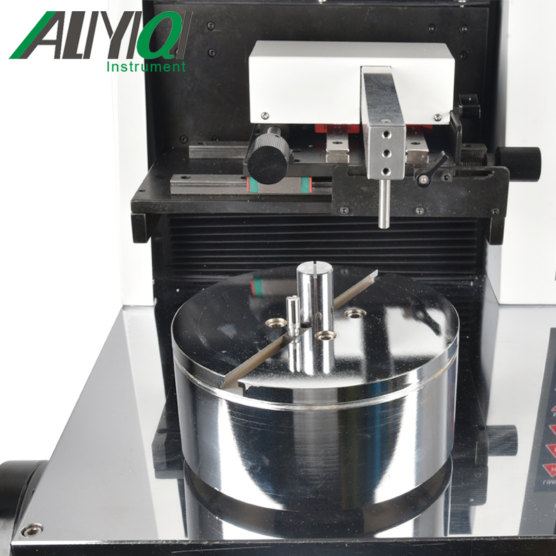
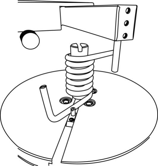
3.3.5 Place the spring on the rotary table, as shown in the figure below:
3.3.6 In the measurement interface, press \"START \" to start the detection, and press \"PRINT \" to print the measurement data when finished.
3.4 Data export
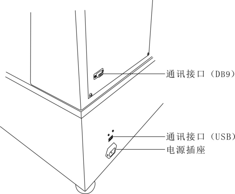
3.4.1Using the communication interface, real-time measurement data can be exported through the communication protocol provided by our company.
Fourth, daily maintenance and maintenance
4.1 The environment should be kept clean to prevent liquids, iron filings, etc. from intruding into the instrument and damaging electronic components.
4.2 Please clean the instrument with a soft cloth, immerse the cloth in the water soaked with detergent, wring it out and remove the dust and dirt.
Note: Do not use volatile chemicals to clean the instrument (such as volatile agent, thinner, alcohol, etc.).
4.3 Do not operate the machine in the following environment
a. Humid environment
b. Dusty environment
c. Where oil or chemicals are used
d. Places with earthquake sources around
4.4 When not in use for a long time, the power plug should be unplugged to prevent dust and moisture.
V. Random accessories